Light guide plate and back light unit including the same

A light guide plate and light source technology, applied in the direction of optical components, optics, light guides, etc., can solve the problems of poor contrast of display devices and poor brightness of backlight units, etc.

Inactive Publication Date: 2012-02-01
LG DISPLAY CO LTD
View PDF3 Cites 12 Cited by
  • Summary
  • Abstract
  • Description
  • Claims
  • Application Information

AI Technical Summary

Problems solved by technology

The resulting dark areas can degrade the brightness of the backlight unit and also degrade the contrast of the display device

Method used


Image

  • Light guide plate and back light unit including the same
  • Light guide plate and back light unit including the same
  • Light guide plate and back light unit including the same

Examples


Embodiment Construction

[0029] Reference will now be made in detail to the preferred embodiments of the invention, examples of which are illustrated in the accompanying drawings. Wherever possible, the same reference numbers will be used throughout the drawings to refer to the same or like parts.

[0030] Hereinafter, a light guide plate and a backlight unit including the light guide plate according to embodiments of the present invention will be described in detail with reference to the accompanying drawings.

[0031] First, refer to Figures 3 to 5 A backlight unit according to an embodiment of the present invention will be described.

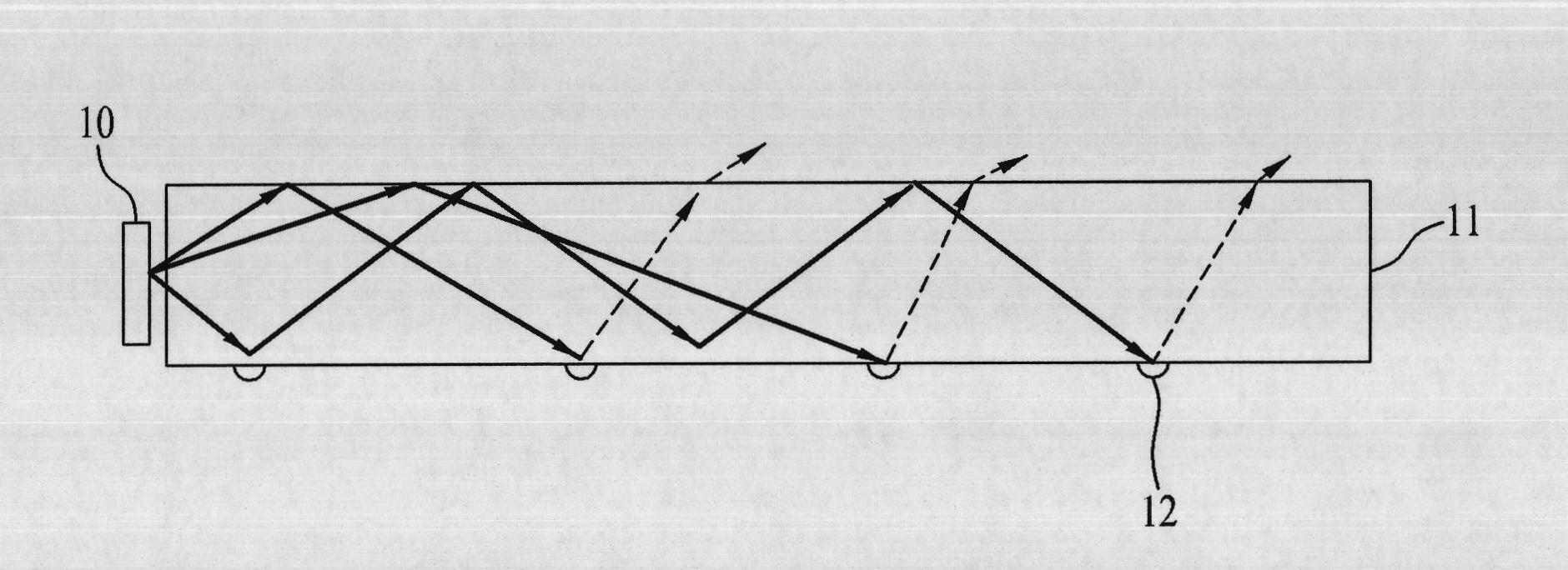
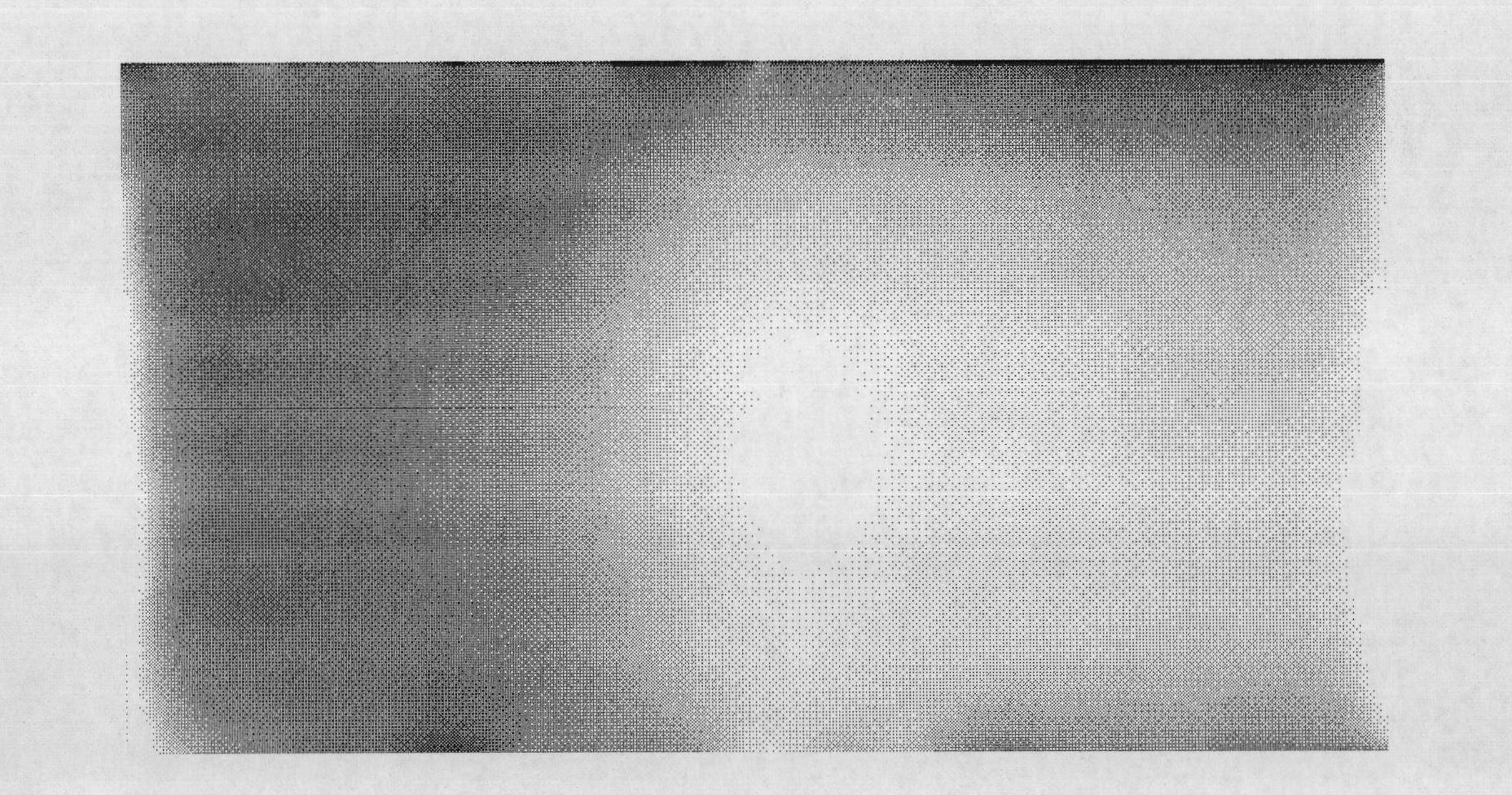
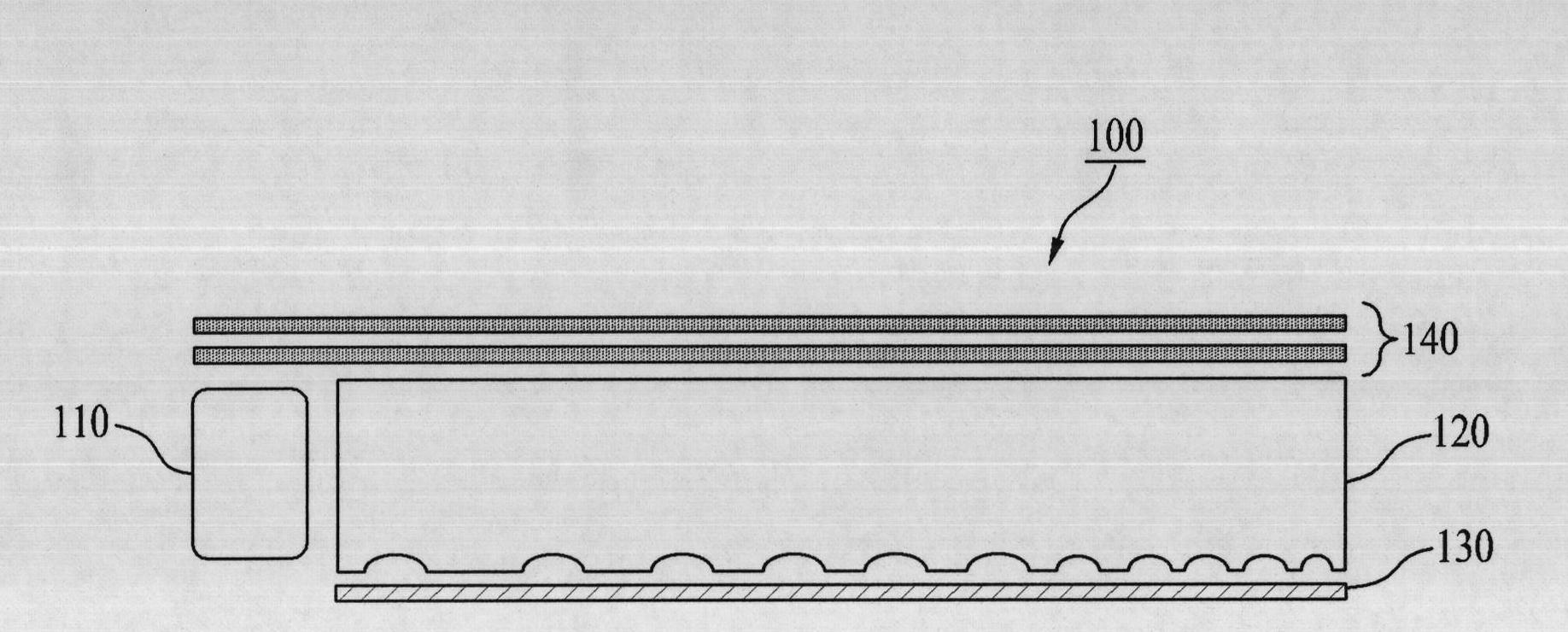
[0032] image 3 is a cross-sectional view of a backlight unit according to an embodiment of the present invention, Figure 4 for image 3 Illuminated view of the backlight unit shown, Figure 5 for image 3Illuminated image of the light guide plate of the backlight unit shown.

[0033] Such as image 3 As shown, the backlight unit 100 according to the embodi...


PUM


Abstract

The invention discloses a light guide plate and a back light unit including the same. A light guide plate having a pattern to minimize generation of a dark zone and a backlight unit including the same are disclosed. The light guide plate includes an intaglio pattern consisting of recesses formed in a surface opposite to a light emitting surface thereof to have a cross section having major-axis and minor-axis diameters and depth, the recesses being spaced apart from one another in first and second directions by first and second distances respectively. The density of the intaglio pattern is directly proportional to the major-axis and minor-axis diameters and depth, and is inversely proportional to the first and second distances. The intaglio pattern has the minimum density in a first region adjacent to a light source, and the maximum density in a second region that is the maximum distance from the light source. A density ratio of the maximum density to the minimum density is 900.

Description

[0001] This application claims priority from Korean Patent Application No. P2010-0068961 filed Jul. 16, 2010, which is hereby incorporated by reference as if fully set forth herein. technical field [0002] The present invention relates to a light guide plate that converts light irradiated from a light source located at a corner thereof into planar light, and a backlight unit including the light guide plate. Background technique [0003] Due to the advancement of information technology, display devices for visually presenting electrical signals containing information have been rapidly developed. With the development of display devices, various flat panel display devices having excellent characteristics such as thin profile, light weight, and low power consumption have been developed and are replacing conventional cathode ray tubes (CRTs). [0004] Specific examples of flat panel display devices include liquid crystal display (LCD) devices, organic light emitting display (OLE...

Claims


Application Information

Patent Timeline
Patent Type & Authority Applications(China)
IPC IPC(8): G02B6/00F21V8/00F21S8/00G02F1/13357
CPCG02B6/0036
Inventor 李东锡金在辰裵俊皓黄龙益李姬暻
Owner LG DISPLAY CO LTD
Why Eureka
Try Eureka