Driver for automatic focusing lens

A driver and automatic technology, applied in the direction of instruments, focusing devices, installation, etc., can solve the problems of reducing the yield of the workpiece, difficult to control, low heat conduction efficiency, etc., to improve the yield of the workpiece, avoid damage to the workpiece, and save cleaning procedures. Effect

Inactive Publication Date: 2012-02-01
LARGAN PRECISION
View PDF2 Cites 4 Cited by
  • Summary
  • Abstract
  • Description
  • Claims
  • Application Information

AI Technical Summary

Problems solved by technology

Using this known method will face the following problems: 1. Since the heating element of the soldering iron for soldering is far away from the area of ​​use, the heat conduction efficiency is low; 2. The soldering tin needs to use flux, which will increase the difficulty of cleaning and also reduce the finished product of the workpiece 3. T

Method used


Image

  • Driver for automatic focusing lens
  • Driver for automatic focusing lens
  • Driver for automatic focusing lens

Examples


Example Embodiment

[0029] The auto-focus lens driver of the present invention will be described in detail through the following specific embodiments with accompanying drawings.

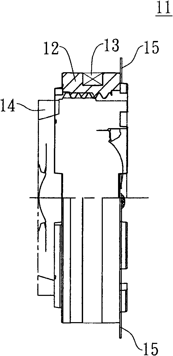
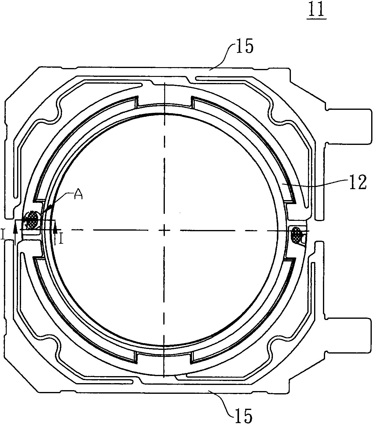
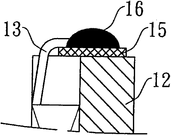
[0030] See Figure 5 versus Image 6 , Respectively show the side view and the rear view of the autofocus lens driver 1 of the present invention, and refer to Figure 7 , Is showing Image 6 An enlarged detailed perspective view of part B in the middle. In this specific embodiment, the auto-focus lens driver 1 of the present invention uses a voice coil motor structure to drive the lens for auto-focusing. The auto-focus lens driver 1 has a fixed side part (not shown) and a movable side part. The fixed side component includes a housing, a yoke made of soft iron and other magnetic materials, and a permanent magnet installed inside the housing and installed on the inner side wall of the yoke. Since the fixed side component is a known structure commonly used in the industry in the voice coil motor structure, in order to avoid t...


PUM

PropertyMeasurementUnit
Areaaaaaaaaaaa

Abstract

The invention provides a driver for an automatic focusing lens, which comprises a movable side part. The movable side part comprises a lens base and two conductive spring plates, wherein the lens base is a hollow cylindrical object; a coil is wound at the outer edge of the cylindrical object; an optical system is accommodated in a hollow part of the cylindrical object; the two conductive spring plates are not connected and are respectively positioned at one side of an optical axis of the cylindrical object; and both ends of the coil are respectively in micro-melting connection with the corresponding conductive spring plates in a hot press mode, wherein the area of a hot press region of the coil is less than 1 square centimetre (mm2).

Description

technical field [0001] The present invention relates to an auto-focus lens driver; in particular, to an auto-focus lens driver applied to a camera module. Background technique [0002] Many electronic devices with photographic functions have the requirement of setting an auto-focus lens driver, such as mobile phones with photographic functions and auto-focus module cameras, etc.; wherein the most commonly used auto-focus lens driver is a Voice Coil Motor (Voice Coil Motor, VCM), the reason is that the voice coil motor can achieve precise displacement, and the price is low, so it is suitable as a short-distance micro-actuator for electronic devices. [0003] see figure 1 and figure 2 , showing a side view and a rear view of a known autofocus lens driver 11, respectively. The known auto-focus lens driver 11 comprises a mirror seat that is a hollow cylindrical body 12, a coil 13 is wound around the outer edge of the cylindrical body 12, and a lens 14 is accommodated in the ...

Claims


Application Information

Patent Timeline
IPC IPC(8): G02B7/09G03B13/36G03B30/00
Inventor 吕俊逸
Owner LARGAN PRECISION
Why Eureka
Try Eureka