Stepping motor control circuit and analog electronic timepiece

A stepping motor, control circuit technology, applied in the direction of motor generator control, electromechanical clocks, clocks and watches, etc., can solve the problems of wrong rotation or non-rotation, unstable driving, low power supply voltage, etc., and achieve the avoidance and avoidance of rotation The effect of static in the middle and reliable needle drive

Inactive Publication Date: 2012-02-01
SEIKO INSTR INC
View PDF2 Cites 6 Cited by
  • Summary
  • Abstract
  • Description
  • Claims
  • Application Information

AI Technical Summary

Problems solved by technology

[0008] Before this standby state, the power supply voltage is low, so the drive is unstable, and the rotor may occasionally stop at an intermediate position different from the normal resting position of the rotor, that is, fall into a so-called intermediate stationary state, resulting in an erroneous determination of rotation or non-rotation problem, and there is a problem of needle movement delay

Method used


Image

  • Stepping motor control circuit and analog electronic timepiece
  • Stepping motor control circuit and analog electronic timepiece
  • Stepping motor control circuit and analog electronic timepiece

Examples


Embodiment Construction

[0024] Next, a stepping motor control circuit according to an embodiment of the present invention and an analog electronic timepiece using the stepping motor control circuit will be described. In addition, in each drawing, the same code|symbol is attached|subjected to the same part.

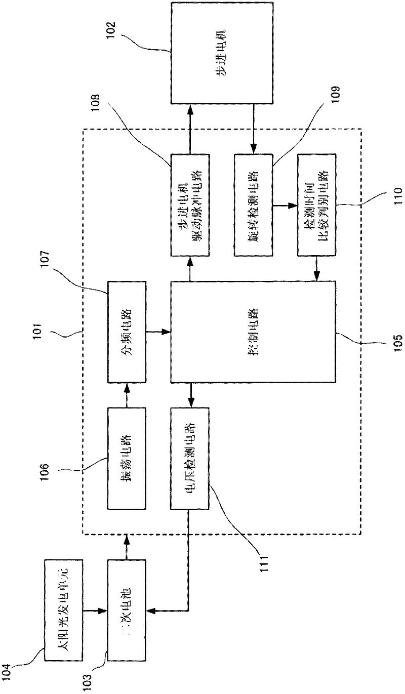
[0025] figure 1 It is a block diagram of an analog electronic timepiece using a stepping motor control circuit according to an embodiment of the present invention, showing an example of an analog electronic wristwatch.

[0026] exist figure 1 Among them, the analog electronic clock has: a stepping motor control circuit 101; a stepping motor 102, which is controlled by the stepping motor control circuit 101 to rotate, and drives the time pointer and the calendar mechanism (not shown) to rotate; as a secondary power supply The battery 103 supplies driving power to circuit elements such as the stepping motor control circuit 101 and the stepping motor 102 ; the solar power generation unit 104 is us...


PUM


Abstract

The invention relates to a stepping motor control circuit and an analog electronic timepiece capable of preventing the halfway stop by accurately determining the rotation status of a stepping motor even when the voltage of a secondary battery used as a power source is lowered. A detection interval in which the rotation status of a stepping motor is divided into a first interval immediately after driving executed by a main driving pulse, a second interval later than the first interval, and a third interval later than the second interval. The driving is executed by a correction driving pulse and the main driving pulse is increased, when a control circuit drives the stepping motor in a driving way different from a driving way at the time of exceeding a predetermined voltage in a case where the voltage of a secondary battery is lowered to be equal to or less than the predetermined voltage and when a rotation detection circuit and a detection time comparison determination circuit detect an induced signal exceeding a first reference threshold voltage in the first interval and the second interval and do not detect the induced signal exceeding a second reference threshold voltage lower than the first reference threshold voltage in the third interval.

Description

technical field [0001] The invention relates to a stepping motor control circuit and an analog electronic clock using the stepping motor control circuit. Background technique [0002] In the past, two-pole PM (Permanent Magnet: Permanent Magnet) type stepping motors were used in electronic equipment such as analog electronic clocks. This stepping motor has: a stator with a rotor housing hole and a positioning part that determines the stop position of the rotor; , which is arranged in the rotor housing hole; and a coil, which generates magnetic flux in the stator by providing an alternating signal to the coil, so that the rotor rotates, and stops the rotor in contact with the positioning part the corresponding location. [0003] As the low-consumption driving method of the two-pole PM type stepping motor, what has been practically applied is the correcting driving method of the stepping motor, which includes the main driving pulse P1 with small energy in general, and when th...

Claims


Application Information

Patent Timeline
Patent Type & Authority Applications(China)
IPC IPC(8): G04C3/14H02P8/02
CPCG04C3/143H02P8/02H02P8/16H02P8/34G04C10/02
Inventor 本村京志间中三郎小笠原健治佐久本和实清水洋山本幸祐神山祥太郎
Owner SEIKO INSTR INC
Why Eureka
Try Eureka