Seamless video display spliced wall

A video display and splicing wall technology, applied in the direction of digital output to display devices, static indicators, identification devices, etc., can solve the problems of large optical waveguide volume, high cost, increase the thickness of the display, etc., and achieve the effect of diluting the gap.

Inactive Publication Date: 2012-02-01
王勇竞
View PDF2 Cites 57 Cited by
  • Summary
  • Abstract
  • Description
  • Claims
  • Application Information

AI Technical Summary

Problems solved by technology

This method is costly and the volume of the optical waveguide is large
2) Rear projection technology is used to achieve seamless splicing effect. Rear projection technology can use edge fusion method to achieve seamless splicing effect, but rear projection technology increases the thickness of the display

Method used


Image

  • Seamless video display spliced wall
  • Seamless video display spliced wall
  • Seamless video display spliced wall

Examples


Embodiment 1

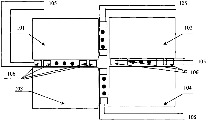
[0025] like figure 1 As shown, several LEDs 106 are placed in the gaps of the video display splicing wall, each LED 106 is connected to a power line and an independent control line 105, and the control line 105 is connected to the main control computer. The corresponding data is sent to each LED, and the color and brightness of the LED 106 are adjusted to match the displayed image outside the gap, so that the gap is no longer visible.

[0026] figure 1 It is a TV splicing wall formed by splicing four identical displays 101 , 102 , 103 , and 104 . The gap in the middle is the gap formed when the displays are spliced. In the figure, a plurality of LEDs 106 are respectively placed in the display gaps of the video display splicing wall, and are respectively connected with the main control computer by independent control lines 105 . The main control computer sends the corresponding data to each LED 106 according to the actual image displayed by the video display splicing wall, a...

Embodiment 2

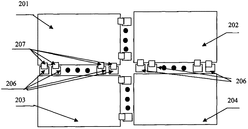
[0028] like figure 2 As shown, several LEDs are placed in the gaps of the video display splicing wall, each LED is connected to a power cord to provide the corresponding power supply, and each LED is connected to an independent light detector, which detects the adjacent display image pixels. The information is transmitted to the LEDs connected to it, and the LEDs display the same color and brightness as the video display video wall. At this time, the LED is like a "chameleon", and the light detector is like a chameleon's sensor, which changes with the change of the adjacent external environment "video display video wall".

[0029] figure 2 It is a splicing video display splicing wall formed by splicing four identical displays 201 , 202 , 203 , and 204 . Different from the first embodiment, each LED 206 placed in the splicing wall slot is not controlled by the main control computer, but by the light detector 207 . A photodetector 207 is integrated on each LED.

[0030] On...

Embodiment 3

[0033] This embodiment is an extension on the basis of the above-mentioned embodiment. It can be applied on the basis of the first embodiment, and can also be applied on the basis of the second embodiment.

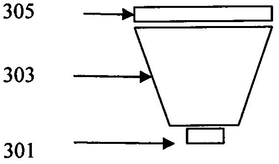
[0034] like Figure 4 As shown, the LEDs further include left and right or upper and lower LEDs, each of the left (or upper) LEDs 407 displays information about adjacent pixels on the left (or upper), and each of the right (or lower) LEDs 406 displays the right (or upper) Bottom) Information about neighboring pixels. In this way, the display gap has more LEDs, and its display resolution is higher.


PUM


Abstract

The invention discloses a seamless video display spliced wall. The seamless video display spliced wall is formed by splicing a plurality of displays; and a plurality of light emitting diodes (LEDs), the brightness and the color of which are matched with the display image conditions of the adjacent displays, are arranged in the spliced seams of the displays. The LEDs are connected with a main control computer through control wires. The main control computer sends corresponding data to each LED according to the actual image displayed by the video display spliced wall, and independently adjusts the LEDs so that the LEDs display the brightness and the color matched with the images displayed by the adjacent displays. Therefore, the purpose of eliminating and reducing the spliced seams between the displays is fulfilled. Or, each LED can be connected with an independent optical detector. The optical detector detects the image information of the adjacent display and transmits the image information to the LED connected with the optical detector, and the LED displays the brightness and the color matched with the image displayed by the adjacent display. The original spliced seams of the video display spliced wall are greatly faded, and an integral effect of seamless splicing is achieved.

Description

technical field [0001] The invention relates to a video display splicing wall, in particular to a seamless video display splicing wall. Background technique [0002] By splicing multiple video display devices together, large-screen display can be realized at low cost, and it has been widely used in many occasions. Since each video display, including liquid crystal display LCD and plasma display PDP, has a physical frame, all video display splicing walls currently have different degrees of splicing gaps, which cannot achieve perfect visual effects. In the future, in order to pursue perfect visual effects, seamless splicing will become the development trend of video display splicing walls. At present, people mainly adopt two ways to achieve the effect of seamless splicing: 1) Using various optical waveguide methods to guide part of the light energy in the display area into the splicing seam. The cost of this method is high, and the volume of the optical waveguide is relative...

Claims


Application Information

Patent Timeline
IPC IPC(8): G09F9/30G06F3/14H05B37/02
CPCG09G3/20G09G3/36G06F3/1446G09G2300/026
Inventor 王勇竞
Owner 王勇竞
Why Eureka
Try Eureka