Body motion detection device and method, as well as radiographic imaging apparatus and method

a motion detection and body technology, applied in the field of body motion detection, can solve the problems of inefficient retake of images, hinder accurate measurement, and inability to properly join the obtained x-ray images, so as to reduce the exposure dose of the subject, efficiently conduct the retake operation, and improve the effect of retake operation

Inactive Publication Date: 2012-03-08
FUJIFILM CORP
View PDF3 Cites 46 Cited by
  • Summary
  • Abstract
  • Description
  • Claims
  • Application Information

AI Technical Summary

Benefits of technology

[0017]The present invention is also directed to preventing occurrence of a body motion during a retake operation, which is conducted after a body motion has occurred in the previous imaging operation, during long-length imaging.
[0067]In particular, in the case where the retake assisting information is displayed, the operator can check the retake assisting information at a glance, and thus can conduct the retake operation more efficiently.

Problems solved by technology

If there is a body motion of the subject between shots, it is impossible to join the obtained X-ray images properly, and this hinders accurate measurement.
In some cases, the operator first notices that a body motion occurred during imaging when the operator is observing the combined image, and it is inefficient to retake the images after all the images have once been taken.
In addition, shots after the occurrence of body motion are of no use and needlessly increase the radiation exposure of the subject.
The problem of body motion may also occur during energy subtraction imaging, where energy subtraction is carried out with using two radiographic images obtained by applying two radiation rays having different energies to a subject based on the fact that the attenuation of radiation transmitted through a subject vary depending on the substances forming the subject, and during temporal subtraction imaging, where a differential image representing a difference between two radiographic images, which are taken at different imaging times, is obtained.
Further, the problem of body motion may also occur during tomosynthesis imaging, where images are taken with moving the X-ray tube to apply the X-ray to a subject from different angles, and the thus obtained images are added up to provide an image in which a desired slice plane is emphasized in order to observe an affected part in more detail, or during continuous shooting to obtain a plurality of images by continuously applying radiation to a subject.
If the subject is, for example, a patient brought to a hospital by the emergency or a patient just after a surgery, the condition of the patient is often severe and it is difficult to hold the body of the patient still in a predetermined position.
Therefore, depending on the condition of the subject, it may be impossible to hold the body still during imaging, and a large body motion may occur in such a case.
Therefore, if the detection of body motion and warning is carried out in a fixed manner, as in the technique disclosed in Japanese Unexamined Patent Publication No. 2009-240656, results of the body motion detection may be non-uniform.
If a large threshold value is set with taking the movement of the heart into account, it may be difficult to detect a body motion when a different part is imaged.
If the body motion correction is conducted when there is a large motion of the subject, the images are excessively corrected and a large distortion is produced, and this may hinder accurate diagnosis.
However, it is impossible to tell how the body motion occurred only from the warning, and a similar body motion may occur again during the retake operation.
If the body motion occurs again during the retake operation, it is necessary to further retake the images, resulting in inefficient imaging and needless increase of the radiation dose of the subject.

Method used


Image

  • Body motion detection device and method, as well as radiographic imaging apparatus and method
  • Body motion detection device and method, as well as radiographic imaging apparatus and method
  • Body motion detection device and method, as well as radiographic imaging apparatus and method

Examples


embodiment claim 1

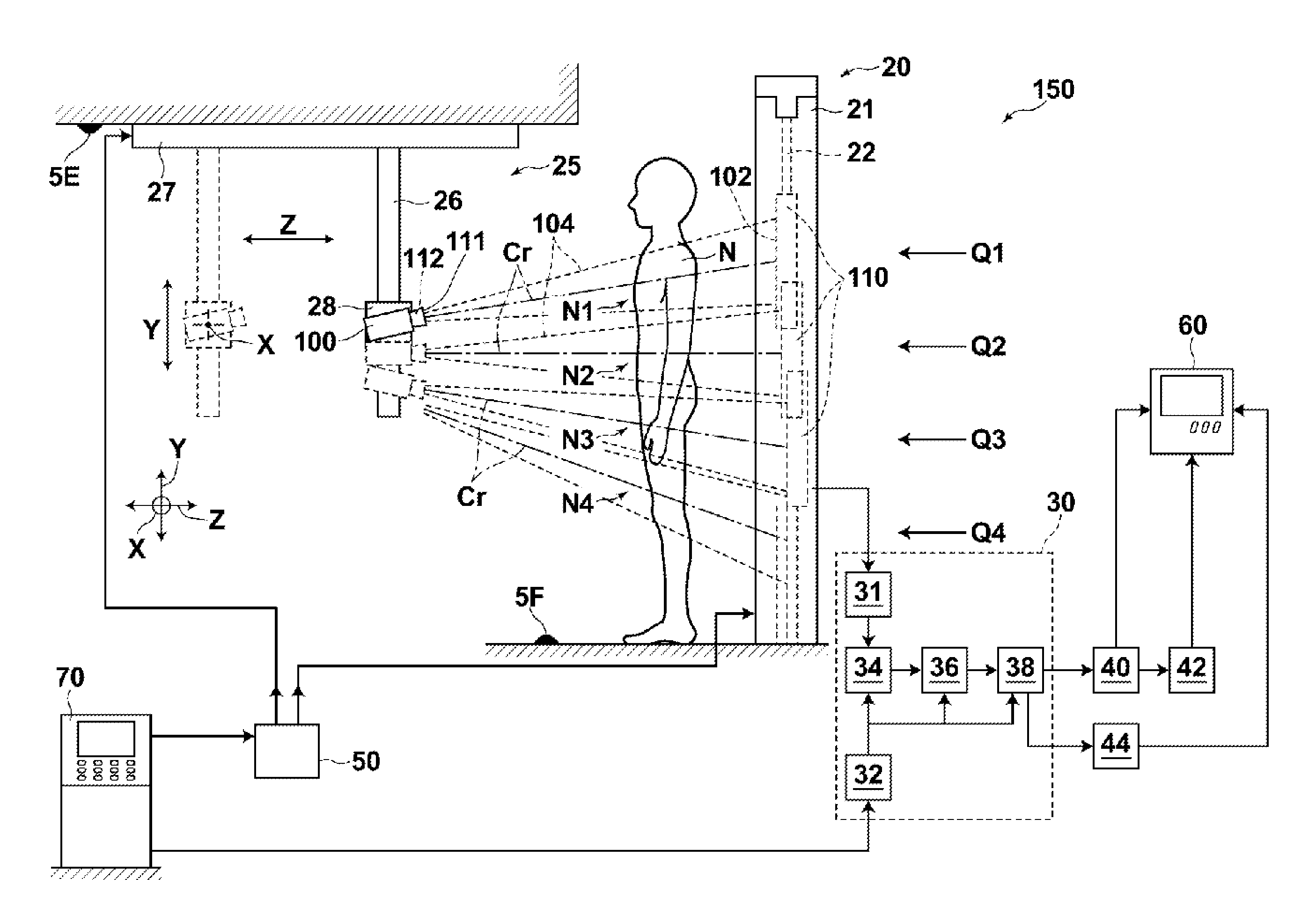
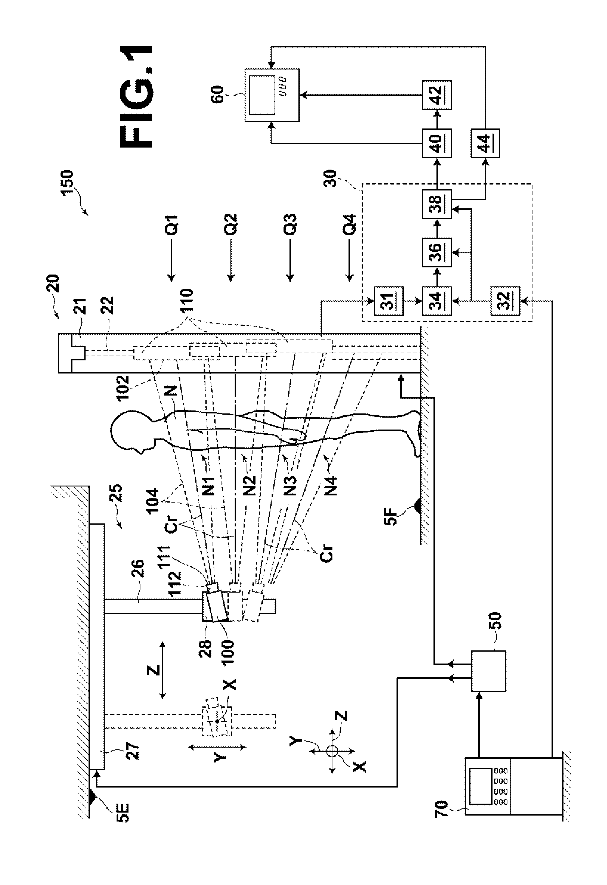
[0226]A body motion detection device comprising:

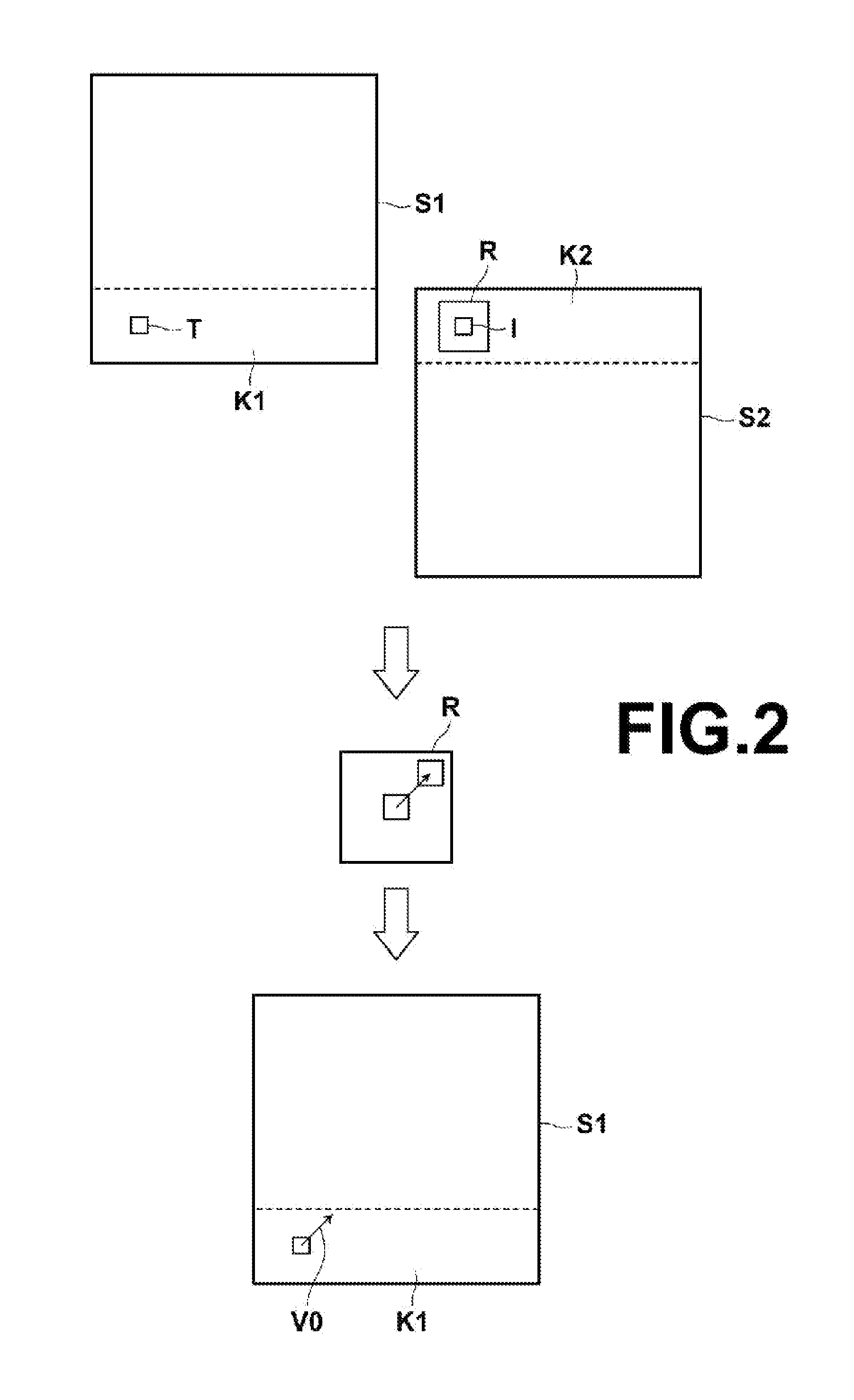
[0227]image obtaining means for obtaining a plurality of radiographic images taken by carrying out a plurality of imaging operations with respect to an identical subject, the radiographic images at least partially overlapping with one another;

[0228]local motion vector calculating means for calculating at least one local motion vector representing a local displacement of the subject in an overlapping area between the radiographic images; and

[0229]body motion index value calculating means for calculating a body motion index value attributed to a posture of the subject based on the local motion vector.

[0230]The “body motion index value attributed to a posture of the subject” refers to an index value of a body motion attributed to a posture of the subject when the subject is regarded as a rigid body, and does not include an index value attributed to a motion of an internal organ, such as the heart, lung, intestine, or the like, inside the ...

embodiment claim 2

[0231]The body motion detection device as defined in embodiment claim 1, wherein the body motion index value calculating means calculates an index value of an amount of parallel displacement of the subject as the body motion index value.

embodiment claim 3

[0232]The body motion detection device as defined in embodiment claim 2, wherein the body motion index value calculating means further calculates at least one of an index value of an amount of three dimensional movement of the subject and an index value of an amount of two dimensional movement of the subject as the body motion index value.


PUM


Abstract

An image obtaining unit obtains a plurality of radiographic images, which at least partially overlap with one another, taken by carrying out a plurality of imaging operations with respect to an identical subject. An imaging information obtaining unit obtains imaging information representing imaging conditions and an imaged subject during the imaging operations. A body motion index value obtaining unit obtains a body motion index value, which indicates a body motion of the subject during imaging of the radiographic images, based on the imaging information.

Description

BACKGROUND OF THE INVENTION[0001]1. Field of the Invention[0002]The present invention relates to body motion detection device and method for detecting a body motion of a subject during imaging from a plurality of radiographic images obtained by carrying out a plurality of imaging operations with respect to the same subject[0003]Further, the present invention relates to radiographic imaging apparatus and method for obtaining a single long-length image by taking a plurality of radiographic images and combining the radiographic images.[0004]2. Description of the Related Art[0005]Conventionally, in the medical field, etc., various types of radiation detectors (so-called “Flat Panel Detectors”, hereinafter “FPDs”), which record a radiographic image with respect to a subject by receiving radiation transmitted through the subject, have been proposed and put to practical use. Among such FPDs, for example, there are FPDs using a semiconductor, such as amorphous selenium, which generates an e...

Claims


Application Information

Patent Timeline
Patent Type & Authority Applications(United States)
IPC IPC(8): A61B5/103A61B6/00
CPCG06T7/20A61B6/02A61B6/4233A61B6/4452A61B6/463A61B6/505A61B6/4464A61B6/5241A61B6/5264A61B6/527A61B6/468A61B6/542A61B6/5229
Inventor YAMAGUCHI, YOSHITAKA
Owner FUJIFILM CORP
Why Eureka
Try Eureka