Self-excitation device for 5KW power-generation welding machine

An electric welding machine, 5KW technology, applied in the direction of synchronous generators, etc., can solve the problems of high cost, low cost and high failure rate of auxiliary excitation

Inactive Publication Date: 2012-02-01
无锡星诺电气有限公司
View PDF4 Cites 2 Cited by
  • Summary
  • Abstract
  • Description
  • Claims
  • Application Information

AI Technical Summary

Problems solved by technology

[0003] The purpose of the present invention is to solve the problems of high cost and high failure rate in auxiliary excitation of flywheel generators at present, and provide a self-excitation device for a 5KW generating electric welding machine, which has the advantages of low cost and low failure rate

Method used


Image

  • Self-excitation device for 5KW power-generation welding machine
  • Self-excitation device for 5KW power-generation welding machine

Examples


Embodiment Construction

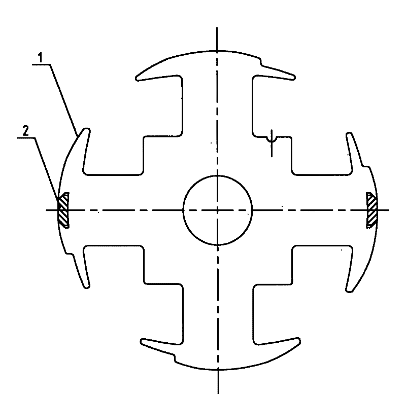
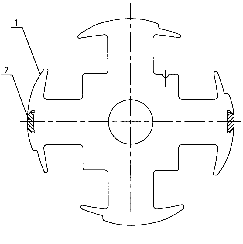
[0012] Such as figure 1 In the shown embodiment, the self-exciting device of the 5KW power generation welding machine includes a permanent magnet 2 installed on the rotor 1 and an auxiliary winding arranged on the stator, and the permanent magnets are symmetrically arranged on the rotor 1 left and right.

[0013] The permanent magnet 2 installed on the rotor 1 generates a magnetic field. During the rotation of the rotor 1, the auxiliary winding installed on the stator cuts the magnetic field lines to generate current, thereby realizing the purpose of power generation. The self-excitation of this 5KW power generation welding machine The device has the advantages of low cost and low failure rate.


PUM


Abstract

The invention discloses a self-excitation device for a 5KW power-generation welding machine. The self-excitation device comprises permanent magnets mounted on a rotor and an auxiliary winding arranged on the rotor, wherein the permanent magnets are arranged on the rotor in bilateral symmetry. Magnetic fields are generated through the permanent magnets mounted on the rotor, and currents are generated by using the auxiliary winding arranged on the rotor to cut magnetic lines of force in a rotating process of the rotor, thus the aim of power generation is realized. The self-excitation device for the 5KW power-generation welding machine disclosed by the invention has the advantages of low cost and difficulty to be in fault.

Description

technical field [0001] The invention relates to a self-exciting device of a 5KW generating electric welding machine. Background technique [0002] The currently commonly used 5KW generating electric welding machine generally adopts a flywheel generator for auxiliary excitation, and its disadvantages are: the cost of the flywheel generator is high, and it is easy to break down, which brings trouble to the use. Contents of the invention [0003] The purpose of the present invention is to solve the problems of high cost and high failure rate of the auxiliary excitation of the flywheel generator at present, and provide a self-excitation device of a 5KW generating electric welding machine, which has the advantages of low cost and low failure rate. [0004] The purpose of the present invention is to realize through the following technical solutions: [0005] A self-exciting device for a 5KW generating electric welding machine includes a permanent magnet installed on the rotor a...

Claims


Application Information

Patent Timeline
Patent Type & Authority Applications(China)
IPC IPC(8): H02K19/28
Inventor 曾元春
Owner 无锡星诺电气有限公司
Why Eureka
Try Eureka