Antenna adjustment method and base station

An adjustment method and base station technology, applied in the directions of antennas, antenna components, wireless communications, etc., can solve the problems of user terminal call drop, network congestion, service quality degradation, etc., and achieve the effect of avoiding congestion and call drop.

Inactive Publication Date: 2012-02-01
ZTE CORP
View PDF3 Cites 23 Cited by
  • Summary
  • Abstract
  • Description
  • Claims
  • Application Information

AI Technical Summary

Problems solved by technology

[0006] The main purpose of the present invention is to provide an antenna adjustment method and a base station to at least solve the above-mentioned problem that if the azimuth angle of the antenna is not adjusted, user terminals in areas with sudden and dense traffic will experience call drop, network congestion, or service failure. quality loss problem

Method used


Image

  • Antenna adjustment method and base station
  • Antenna adjustment method and base station
  • Antenna adjustment method and base station

Examples


Embodiment 1

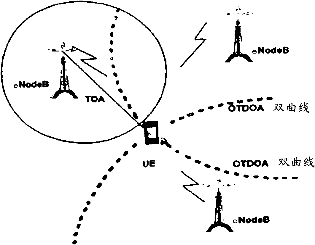
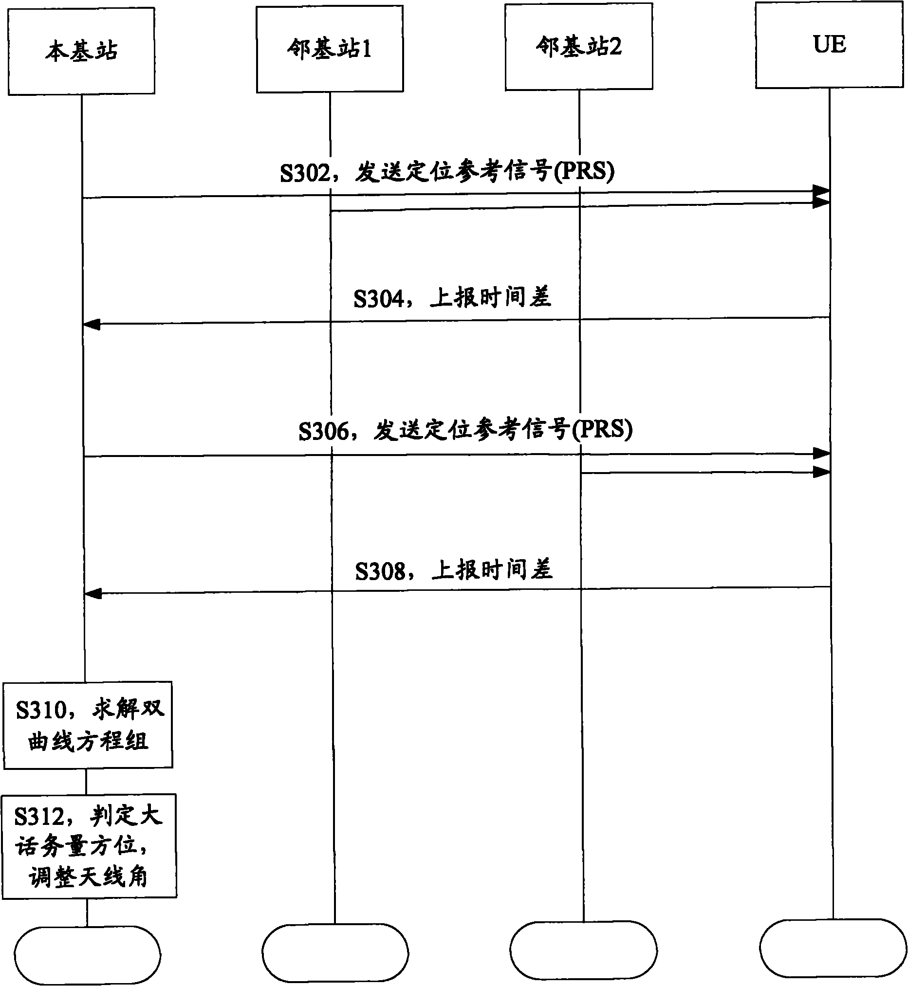
[0030] Such as image 3 As shown, taking a case where a user calls and complains about a call drop or congestion in a certain location due to heavy traffic (manual triggering) as an example, the base station uses OTDOA technology to locate and obtain the user's location coordinates (that is, the UE used by the user) in detail. ) The specific steps are as follows:

[0031] From step S302 to step S304, the initial condition is that the base station has location information of two neighboring base stations (neighboring base station 1 and neighboring base station 2). The base station and the adjacent base station 1 synchronously send positioning reference signals to the UE, and the UE obtains TDOA (Time Difference Of Arrival, time difference of arrival) and reports it to the base station; the base station calculates the distance from the UE to the base station and the adjacent base station 1 based on TDOA. The distance difference, and according to the distance difference to list ...

Embodiment 2

[0039] Embodiment 2 When congestion or call drop occurs in multiple UEs (automatic trigger)

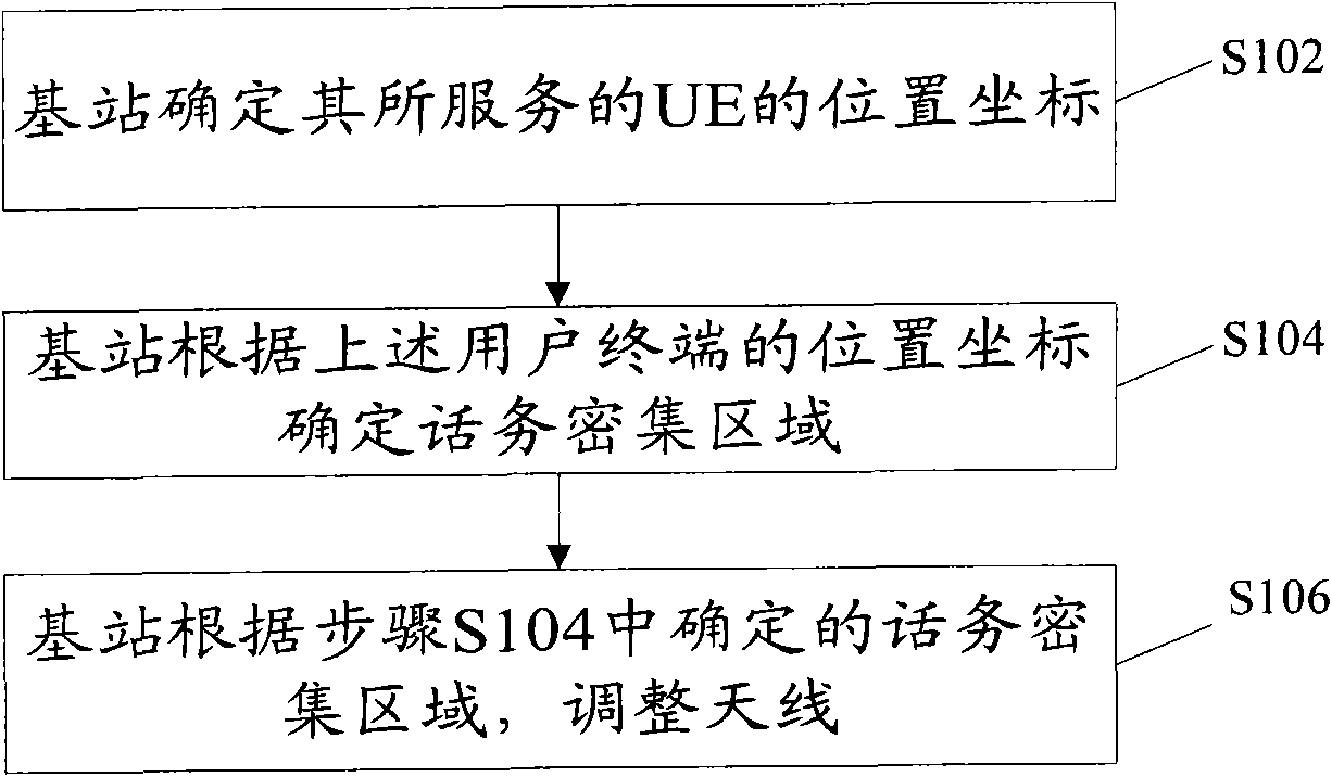
[0040] Step 1, obtain the position coordinates of multiple UEs, and the process of obtaining the position coordinates of each UE is the same as image 3 Step S302 to step S310 in. This step corresponds to figure 1 Step S102 in.

[0041] Step 2, calculate the angle of the position of each UE (coordinates can also be converted into radians);

[0042] Specifically, firstly, a coordinate system is established with the base station as the origin and a predetermined direction (such as the due east direction) as the x-axis, and the position coordinates of multiple UEs calculated in the above step 1 are converted into new positions in the coordinate system coordinates; then, according to the new position coordinates of each UE, calculate the included angle between the connection line between each UE and the base station and the above-mentioned x-axis, and obtain the position angle of each ...

Embodiment 3

[0048] Embodiment 3 Periodically adjust the antenna azimuth angle according to the traffic distribution (periodic triggering)

[0049] Step 1. Adjustment can be made in advance when transfer occurs in a large traffic area, instead of waiting until congestion or call drop occurs, so as to prevent problems before they happen. Obtain the position coordinates of all active UEs, and the process of obtaining the position coordinates of each UE is the same as image 3 Step S302 to step S310 in. This step corresponds to figure 1 Step S102 in.

[0050] Step 2, calculate the angle of the position of each UE (coordinates can also be converted into radians);

[0051] Step 3: Divide the cell corresponding to the base station into several equal parts, and judge whether there is an area with dense traffic. If 30° is used as an area (also called a sub-sector), the cell covered by the omnidirectional antenna can be divided into 12 equal parts. The area division of omnidirectional antenna ...


PUM


Abstract

The invention discloses an antenna adjustment method and a base station, wherein the method comprises the steps that: the base station determines the position coordinate of a user terminal that the base station serves; the base station determines a traffic-intensive area according to the position coordinate of the user terminal; and the base station adjusts the azimuth angle of an antenna according to the traffic-intensive area. The invention determines the traffic-intensive area by conducting statistics to the position of user equipment (UE) so as to adjust the angle of the antenna, adapt to the changes of traffic distribution and avoid congestion and cut-off.

Description

technical field [0001] The present invention relates to the communication field, in particular, to an antenna adjustment method and a base station. Background technique [0002] The adjustment of antenna angle is very important to the network quality of mobile communication. On the one hand, accurate azimuth and inclination can ensure that the actual coverage of the base station is the same as expected and ensure the operation quality of the entire network; on the other hand, proper adjustment of the angle according to specific application conditions can better optimize the existing mobile communication network. [0003] In the construction of a mobile communication network, the angle of the antenna is generally planned according to factors such as cell coverage, cell capacity, and geographical features. This is also one of the important standards for antenna installation. If the angle setting deviates from it, it will easily lead to The actual coverage of the base station...

Claims


Application Information

Patent Timeline
Patent Type & Authority Applications(China)
IPC IPC(8): H04W16/28H04W28/02H04W64/00H04W88/08
CPCH01Q3/26H04W24/02H04W72/046H01Q1/246
Inventor 卫建国张现周
Owner ZTE CORP
Why Eureka
Try Eureka