Propeller Fan

A technology for propellers and fans, applied in the field of propeller fans, can solve problems such as deterioration of air supply-noise characteristics, and achieve the effects of improving air supply-noise characteristics and suppressing eddy currents on the outer edge of blades

Active Publication Date: 2012-02-01
MITSUBISHI ELECTRIC CORP
View PDF7 Cites 13 Cited by
  • Summary
  • Abstract
  • Description
  • Claims
  • Application Information

AI Technical Summary

Problems solved by technology

[0006] However, according to the above-mentioned conventional technology, a large blade outer edge vortex is generated at the blade outer edge.
Therefore, there is a problem that the air blowing-noise characteristic deteriorates

Method used


Image

  • Propeller Fan
  • Propeller Fan
  • Propeller Fan

Examples


Embodiment approach 1

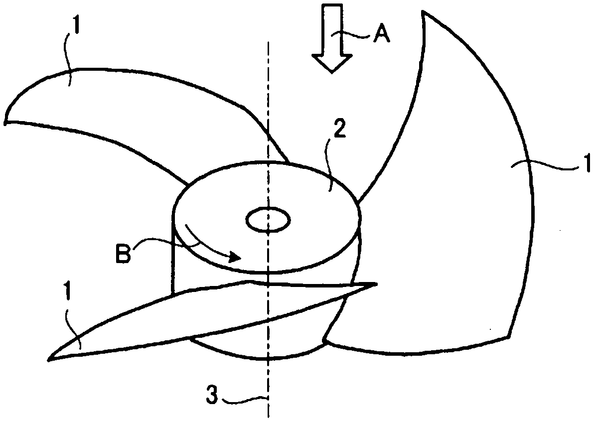
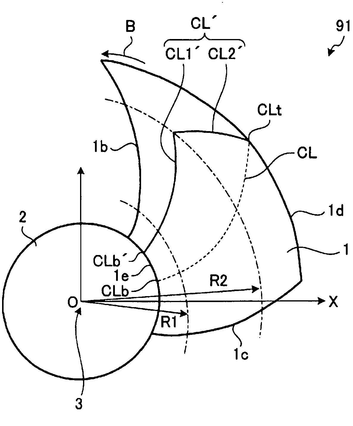
[0034] figure 1 It is a perspective view showing a general propeller fan, diagram 2-1 It is a plan view of the propeller fan according to Embodiment 1 of the present invention, Figure 2-2 It is a cylindrical cross-sectional view of the first region of the blade of Embodiment 1.

[0035] figure 1 The shown propeller fan has three blades, but the number of blades is not limited in the present invention, and other multiple numbers may be used. In the following description, the shape of one blade will be mainly described, and the shapes of other blades are also the same.

[0036] Such as figure 1 As shown, the blades 1 having a three-dimensional shape are radially mounted on the outer periphery of a cylindrical hub 2 , and the hub 2 is driven to rotate by a motor (not shown) to rotate in the direction of rotation B around the rotating shaft 3 . In addition, the hub 2 is cylindrical, but the blades 1 may be radially formed on the outer peripheral portion of the hub formed by...

Embodiment approach 2

[0053] Image 6 It is a perspective view showing a propeller fan 92 having a blade 21 according to the second embodiment. The blade 21 according to the second embodiment has the leading edge side of the blade inner peripheral portion of the blade having the maximum arc height ridge line CL' of the first embodiment formed in a wave shape 21m. . The waveform of the blade leading edge 21b becomes a maximum waveform, and gradually becomes a small waveform toward the blade center portion.

[0054] Figure 7 is indicative of Image 6 The perspective view of the airflow on the negative pressure surface side of the blade 21 according to Embodiment 2 is shown. Such as Figure 7 As shown, in the air flowing into the leading edge 21b of the blade, the wave 21m of the blade 21 generates a longitudinal vortex flow, making the airflow E2 around the inner periphery of the blade a less turbulent airflow E2, thereby reducing the noise caused by the turbulence of the airflow.

Embodiment approach 3

[0056] Figure 8 It is a perspective view showing a propeller fan 93 having a blade 31 according to the third embodiment. The blade 31 according to the third embodiment has a blade inner peripheral trailing edge side of the blade having the maximum camber ridge line CL' of the first embodiment formed in a wave form 31 m . The waveform of the blade trailing edge 31c is a maximum waveform, and gradually becomes a small waveform toward the blade center portion.

[0057] Figure 9 is indicative of Figure 8 The perspective view of the airflow on the negative pressure surface side of the vane 31 according to Embodiment 3 is shown. Such as Figure 9 As shown, the longitudinal vortex generated by the wave form 31n of the blade 31 can reduce the turbulence of the air caused by the vortex generated at the trailing edge 31c of the blade, and become the airflow E3 with less turbulence, thereby reducing the turbulence caused by the turbulence of the airflow. caused noise.

[0058] ...


PUM


Abstract

Provided is a propeller fan comprising a hub fitted on a spindle, and a plurality of wings mounted radially on the hub for blowing a wind in the spindle direction. In a first region of the wing from the spindle to a predetermined radius, the edge line of the maximum camber in the cylindrical section of the wing, which is cut from the spindle along an arbitrary radius, is within 50 % of a wing chord length from a wing front edge. In a second region of the wing from the predetermined radius to a wing outer-edge, the edge line of the maximum camber in the cylindrical section of the wing, which is cut from the spindle along the arbitrary radius, is connected at the predetermined radial position to the edge line of the maximum camber of the first region, and is positioned, as radially enlarged, on the side of a wing trailing-edge, so that the edge line is within 50 % of the wing chord length from a wing front edge at the wing outer-edge.

Description

technical field [0001] The present invention relates to propeller fans used for ventilation fans, air conditioners and the like. Background technique [0002] Conventionally, a propeller fan has been disclosed in which a plurality of blades are provided on the outer peripheral portion of a hub attached to a rotating shaft, and in a cylindrical cross section of the blades cut along an arbitrary radius from the rotating shaft, the position where the amount of warping is the largest It is located on the trailing edge side of the blade as the radius increases (for example, refer to Patent Document 1). [0003] In addition, an axial flow fan is also disclosed, which has a hub rotating under a driving force and blades connected around the hub, the blades are thin-walled blades and have warpage, and the maximum arc height of the warpage camber) is set within a range of 5% to 8% of the chord length of the blade, and the maximum camber position is set within a range of 20% to 40% of...

Claims


Application Information

Patent Timeline
Patent Type & Authority Applications(China)
IPC IPC(8): F04D29/38F04D29/66
CPCF04D29/384F05D2240/307F04D19/00F04D29/38F04D29/66
Inventor 新井俊胜中岛诚治菊地仁盐野入公宣荒木克己
Owner MITSUBISHI ELECTRIC CORP
Why Eureka
Try Eureka