Intelligent monitoring camera apparatus and image monitoring system implementing same

A technology for surveillance cameras and remote control devices, which is applied to closed-circuit television systems, components of television systems, image communication, etc., can solve the problems of increased computational burden, increased system complexity, and inability to use PTZ cameras, and achieves data processing. The effect of reducing the burden, minimizing the cost of upgrading, and reducing the burden of data processing

Inactive Publication Date: 2012-02-01
YOUNG KOOK ELECTRONICS
View PDF4 Cites 46 Cited by
  • Summary
  • Abstract
  • Description
  • Claims
  • Application Information

AI Technical Summary

Problems solved by technology

[0008] In particular, in the analog image transmission process, since the video signal obtained by each camera is transmitted to the remote monitoring unit through its own line, there is a problem that cable laying costs and maintenance management costs increase as the number of cameras increases.
In this case, even if the bandwidth is large enough, in order to transmit the video signals from each camera through lines less than the number of cameras, multiplexers should be installed at places where the lines are concentrated and the remote monitoring unit should have demultiplexer, thereby increasing system complexity
In order to get rid of this system complexity, although the video signals from each camera can be transmitted as one image through the mirror mixer, the image quality of each camera is reduced due to the synthesis of the images of each camera into one screen. Decline, when the user only selects the necessary image and enlarges it to full screen, etc., the other images other than the selected image cannot be monitored
[0009] In addition, in the case of network image transmission, since each image is converted into network data and transmitted to the remote monitoring unit, as the number of cameras increases, the communication bandwidth and the computational burden of processing these images also increase.
[0010] On the other hand, for example, when converting a monitoring system with only PTZ cameras to the above-mentioned monitoring system combining panoramic cameras and PTZ cameras, existing equipment cannot be used smoothly.
That is, the standard of the camera before and after the system conversion, for example, if the existing system structure is an analog system and then converted to a network system, and the possibility of interoperability is low due to the difference in structure, the PTZ camera cannot be used, and only the new system can be used. Additional camera for replacement
In particular, the aforementioned computational burden on PTZ camera control or network-based image transmission may even necessitate replacement of the control equipment constituting the remote monitoring unit, such as the PC itself

Method used


Image

  • Intelligent monitoring camera apparatus and image monitoring system implementing same
  • Intelligent monitoring camera apparatus and image monitoring system implementing same
  • Intelligent monitoring camera apparatus and image monitoring system implementing same

Examples


Embodiment Construction

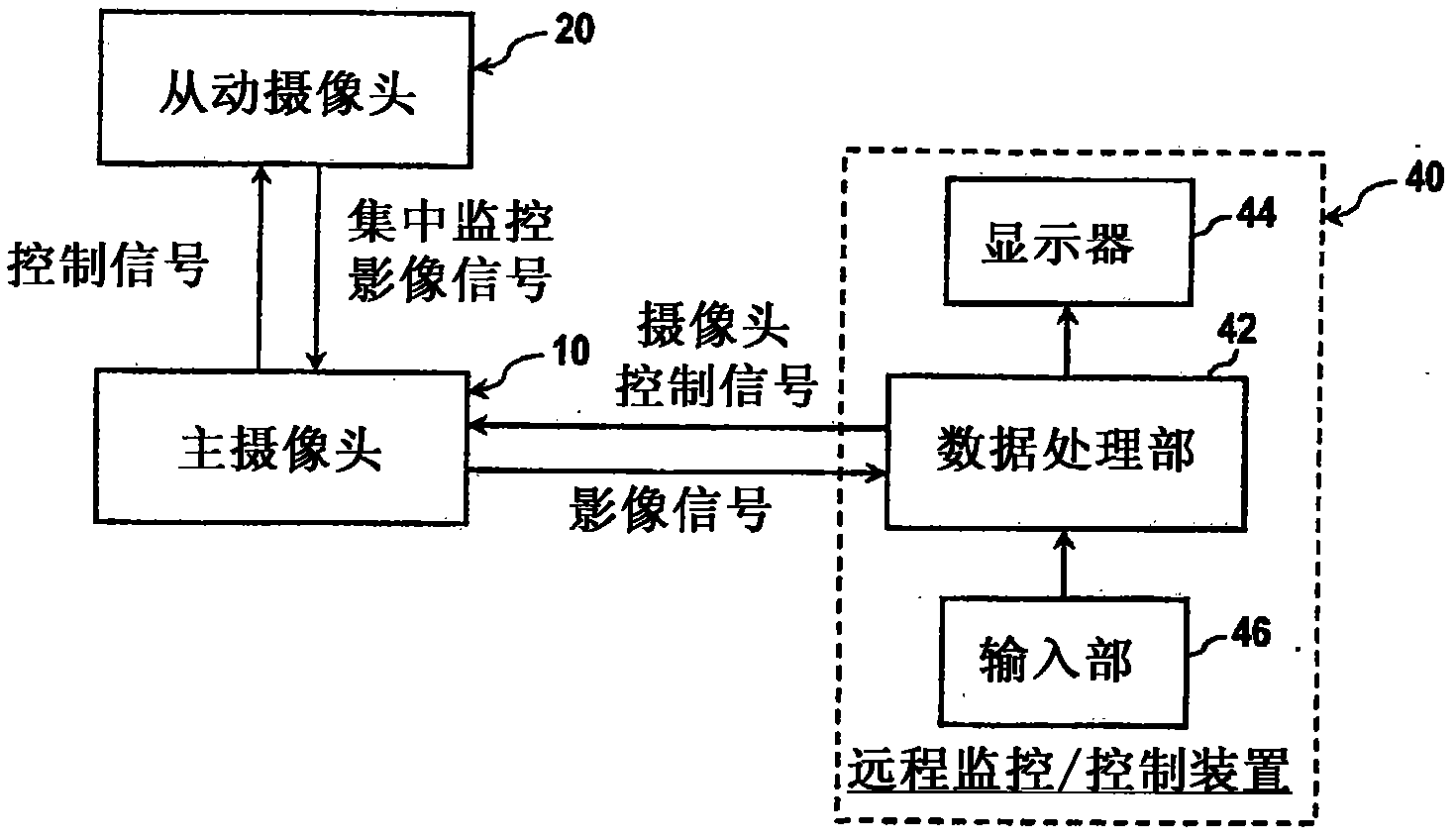
[0078] figure 1 One embodiment of the video monitoring system according to the present invention is shown. The image monitoring system according to the present invention includes a master camera 10 , a slave camera 20 , and a remote monitoring / control device 40 .

[0079] The main camera 10, as the intelligent monitoring camera device according to the present invention, shoots the monitoring area in all directions, detects the dynamic object from the omnidirectional image of the camera, and controls the slave camera 20 to make it concentrate on shooting when the dynamic object is detected. area. Also, the main camera 10 generates an output image by synthesizing the centralized monitoring image and the omnidirectional image obtained by the slave camera 20 , and supplies it to the remote monitoring / control device 40 as an analog video signal or a digital video signal.

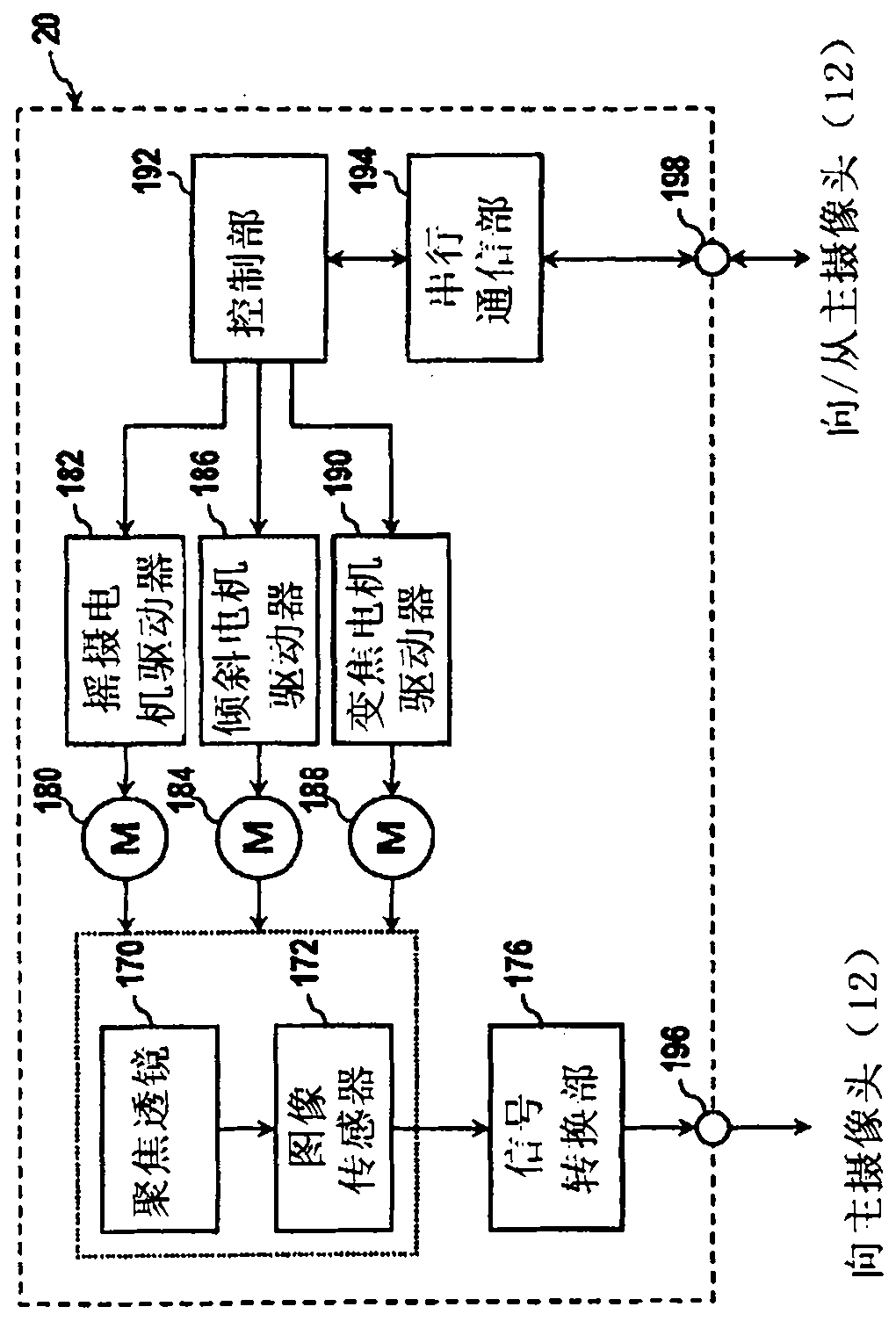
[0080] The slave camera 20 receives a control signal from the master camera 10 through serial communication,...


PUM


Abstract

The present invention relates to a monitoring camera apparatus which directly detects motion in an image to control the pan / tilt / zoom of a centralized monitoring camera, and which transmits a wide area monitoring image and a centralized monitoring image together to a control device in a remote place, and also relates a remote monitoring system using same. The monitoring camera apparatus acquires monitoring images to be displayed in a remote control device (40), and controls a centralized monitoring imaging unit (20) without the assistance of the remote control device (40). The monitoring camera apparatus comprises a wide angle imaging unit (110), a control and signal-processing unit (120), and signal-transmitting units (160, 162). The wide angle imaging unit (110) acquires a wide angle image for a monitoring area. The control and signal-processing unit (120) detects the location of a moving object from the wide angle image, generates a control signal corresponding to the location information of the moving object to control the centralized monitoring imaging unit (20) to photograph the moving object, and receives the centralized monitoring image acquired by the centralized monitoring imaging unit (20). The signal-transmitting units (160, 162) transmit the monitoring image containing the centralized monitoring image to the remote control device (40).

Description

technical field [0001] The present invention relates to an imaging device, and more specifically relates to an imaging device that can be used in a monitoring system of a closed-circuit television (CCTV, closed-circuit television) system. In addition, the present invention also relates to a monitoring system using such a camera device. Background technique [0002] Generally, a CCTV monitoring system includes: a camera, which shoots the area to be monitored; a remote monitoring unit, which displays the image captured by the camera on a display and stores it in a storage device. The operation of the camera is controlled by the remote monitoring unit, and the acquired image is transmitted to the remote monitoring unit via a coaxial cable in a composite video signal suitable for example NTSC, PAL or SECAM standard or as a component video signal or a compressed video signal. [0003] Various types of surveillance cameras are widely used today, but one of the most widely used ca...

Claims


Application Information

Patent Timeline
Patent Type & Authority Applications(China)
IPC IPC(8): H04N7/18H04N5/225
CPCH04N5/23238G08B13/19643H04N7/181H04N7/188H04N5/247H04N5/23296H04N7/183H04N23/698H04N23/69H04N23/90
Inventor 金培薰李智焕
Owner YOUNG KOOK ELECTRONICS
Why Eureka
Try Eureka