Method for manufacturing nozzle distributor of reaction vessel

A production method and reactor technology, which is applied in the production field of reactor nozzle distributors, can solve the problems of small atomization area, atomization can not fill the reactor space, and uneven space distribution, so as to achieve high atomization area and improve transparency , The effect of uniform liquid injection

Active Publication Date: 2014-03-26
SHANGHAI TAIJIE CHEM
View PDF4 Cites 0 Cited by
  • Summary
  • Abstract
  • Description
  • Claims
  • Application Information

AI Technical Summary

Problems solved by technology

[0005] The invention provides a method for making a nozzle distributor for a reactor. Using the distributor manufactured by the invention, the distribution of liquid flow pipes and nozzles is reasonable, which solves the problem of small atomization area and uneven spatial distribution of ordinary nozzle distributors. Disadvantages such as uniformity and atomization cannot fill the entire reactor space

Method used


Image

  • Method for manufacturing nozzle distributor of reaction vessel
  • Method for manufacturing nozzle distributor of reaction vessel

Examples


Embodiment approach ( 1

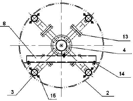
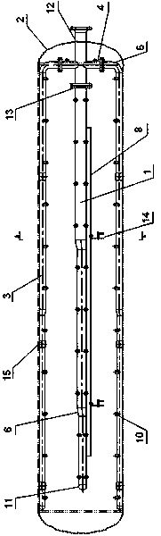
[0021] The method for making the reactor nozzle distributor provided by the present invention, the parts used include the feed port 12, the connecting pipe 4, the elbow 5 and a plurality of liquid flow pipes, wherein the number of the liquid flow pipes can be selected according to the volume of the reaction kettle , such as 1, 3, 5, 9, 13, 17, etc.

[0022] Its production steps are as follows:

[0023] Step 1, install the connecting pipe 4 on the feeding port 12, make one of them on the same straight line as the feeding port, and use it as an intermediate connecting pipe; make the other connecting pipes vertical to the feeding port, and arrange them radially with the feeding port as the center ;

[0024] Step 2, install the elbow 5 on the connecting pipe arranged radially;

[0025] Step 3, install a liquid flow pipe on the intermediate connecting pipe as the intermediate pipe 1; install other liquid flow pipes on the elbow 5 one by one as the peripheral pipe 3, and make the ...

Embodiment approach ( 2

[0029] On the basis of the embodiment (1), the liquid flow pipeline is made into a gradually tapered pipeline, and two adjacent pipeline sections with different diameters are connected by a different-diameter joint 11 . Wherein, the reducing joint may be an eccentric reducing joint or a concentric reducing joint. Steps 1 to 5 are the same as in Embodiment (1).

[0030] Step 6, fixing the intermediate pipe 1 on the crossbeam 8 through the angle steel, and fixing the crossbeam on the inner wall 2 of the reactor through the support member 14 . Wherein, the above-mentioned angle steel is fixedly connected to the crossbeam through full thread bolts, nuts and square inclined washers.

[0031] Step 7, fix the peripheral pipe 3 on the inner wall 2 of the reactor through the hoop 15, and engage the hoop through the full thread bolt, nut and square washer.

[0032] Taking the synthesis of fatty alcohol polyoxyethylene ether as an example, the reactor nozzle distributor made by the abo...


PUM


Abstract

The invention provides a method for manufacturing a nozzle distributor of a reaction vessel. The method comprises the following steps: 1, connecting five to thirteen liquid pipelines to a feed inlet; 2, arranging a plurality of sockets with openings with different orientations on each liquid pipeline in a malposed manner; and 3, arranging a nozzle on each socket. Experiments and uses prove that the nozzle distributor of the reaction vessel manufactured with the method of the invention has the advantages of high atomization area and large atomization volume, and can satisfactorily increase and improve the transparency and the color of products, and the reaction conversion rate.

Description

technical field [0001] The invention relates to a manufacturing method of a chemical reaction kettle part, in particular to a manufacturing method of a nozzle distributor of a reaction kettle. Background technique [0002] Reactor is a very important equipment in petrochemical and fine chemical industry, its main function is to complete the corresponding chemical reaction in the equipment. As a relatively advanced type of reactor, the circulating spray reactor has a great impact on the quality of the products produced by the atomization effect of the liquid reactants in the reactor, because the liquid reactants are in the same Under the process conditions, the atomization effect is determined by the nozzle of the reactor and the distributor of the nozzle. [0003] The nozzle distributors of ordinary reactors are mostly in the shape of a "one" or ring shape, the atomization effect is relatively poor, the atomization area is small, the space distribution is uneven, and the at...

Claims


Application Information

Patent Timeline
Patent Type & Authority Patents(China)
IPC IPC(8): B01J19/26
Inventor 方剑
Owner SHANGHAI TAIJIE CHEM
Why Eureka
Try Eureka