Improved electric drill

An electric drill and combined technology, applied in portable drilling rigs, drilling/drilling equipment, metal processing equipment, etc., can solve the problems of difficult operation, inconvenient application, inconvenient power cord carrying, etc., to achieve convenient wire collection and use The effect of convenience, fast transportation and convenient transportation

Inactive Publication Date: 2012-02-08
曹兴元
View PDF0 Cites 1 Cited by
  • Summary
  • Abstract
  • Description
  • Claims
  • Application Information

AI Technical Summary

Problems solved by technology

[0002] In the past electric drills, it was inconvenient to carry because the power cord was very long, and in daily use, the power cord was not too short to make the operation difficult to implement, and the user needed to trigger the drill during use. Only the switch can be powered on, so sometimes it is not convenient to apply

Method used


Image

  • Improved electric drill
  • Improved electric drill

Examples


Embodiment Construction

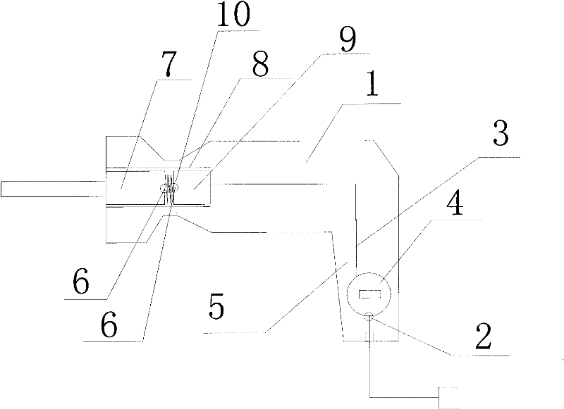
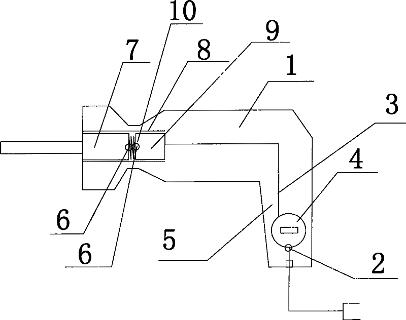
[0010] Such as figure 1 An improved electric drill includes an electric drill main body 1, a handle 5 and a power cord 3, the top of the electric drill is provided with a chute 8, and the chute 8 is provided with a motor mechanism 7 and a trigger mechanism 9, and the motor mechanism 7 A contact 6 is provided at one end of the handle, a spring 10 is provided between the motor mechanism 7 and the trigger mechanism 9, a wire storage device 4 is provided inside the handle 5, and a power cord is provided on one side of the wire storage device 4 hole 2 , the power cord 3 passes through the power cord hole 2 and the bottom of the cord storage device 4 and is connected with the trigger mechanism 9 .


PUM


Abstract

The invention relates to an improved electric drill, which comprises an electric drill main body, a handle and a power line, wherein the top of the electric drill is provided with a chute; a motor mechanism and a trigger mechanism are arranged in the chute; one end of the motor mechanism is provided with a contact; a spring is arranged between the motor mechanism and the trigger mechanism; a line storage device is arranged in the handle; a power line hole is formed on one side of the line storage device; and the power line passes through the power line hole and the bottom of the line storage device and is connected with the trigger mechanism. The improved electric drill has the advantages that: the line is convenient to wind up, transportation is facilitated, and the electric drill is convenient to use.

Description

technical field [0001] The present invention relates to an improved electric drill. Background technique [0002] In the past electric drills, it was inconvenient to carry because the power cord was very long, and in daily use, the power cord was not too short to make the operation difficult to implement, and the user needed to trigger the drill during use. Only the switch can be powered on, so sometimes it cannot be conveniently applied. Contents of the invention [0003] The object of the present invention is to provide an improved electric drill. [0004] The technical scheme adopted in the present invention is: [0005] An improved electric drill, comprising an electric drill main body, a handle and a power cord, the top of the electric drill is provided with a chute, the chute is provided with a motor mechanism and a trigger mechanism, and one end of the motor mechanism is provided with a contact, so A spring is provided between the motor mechanism and the trigger ...

Claims


Application Information

Patent Timeline
Patent Type & Authority Applications(China)
IPC IPC(8): B23B45/02
Inventor 曹兴元
Owner 曹兴元
Why Eureka
Try Eureka