Cleaning equipment of drainage pipeline

A technology for cleaning equipment and drainage pipes, applied in the field of cleaning, can solve the problems of heavy cleaning workload and low cleaning efficiency, and achieve the effects of convenient operation, improved work efficiency, and increased flushing

Inactive Publication Date: 2018-03-16
孙建军
View PDF0 Cites 1 Cited by
  • Summary
  • Abstract
  • Description
  • Claims
  • Application Information

AI Technical Summary

Problems solved by technology

[0004] The purpose of the present invention is to solve the problems of low cleaning efficiency and heavy cleaning workload of cleaning equipment in the prior art, and propose a cleaning equipment for drainage pipes

Method used


Image

  • Cleaning equipment of drainage pipeline
  • Cleaning equipment of drainage pipeline
  • Cleaning equipment of drainage pipeline

Examples


Embodiment Construction

[0021] The following will clearly and completely describe the technical solutions in the embodiments of the present invention with reference to the accompanying drawings in the embodiments of the present invention. Obviously, the described embodiments are only some, not all, embodiments of the present invention.

[0022] In describing the present invention, it should be understood that the terms "upper", "lower", "front", "rear", "left", "right", "top", "bottom", "inner", " The orientation or positional relationship indicated by "outside", etc. is based on the orientation or positional relationship shown in the drawings, and is only for the convenience of describing the present invention and simplifying the description, rather than indicating or implying that the referred device or element must have a specific orientation, so as to Specific orientation configurations and operations, therefore, are not to be construed as limitations on the invention.

[0023] refer to Figure ...


PUM


Abstract

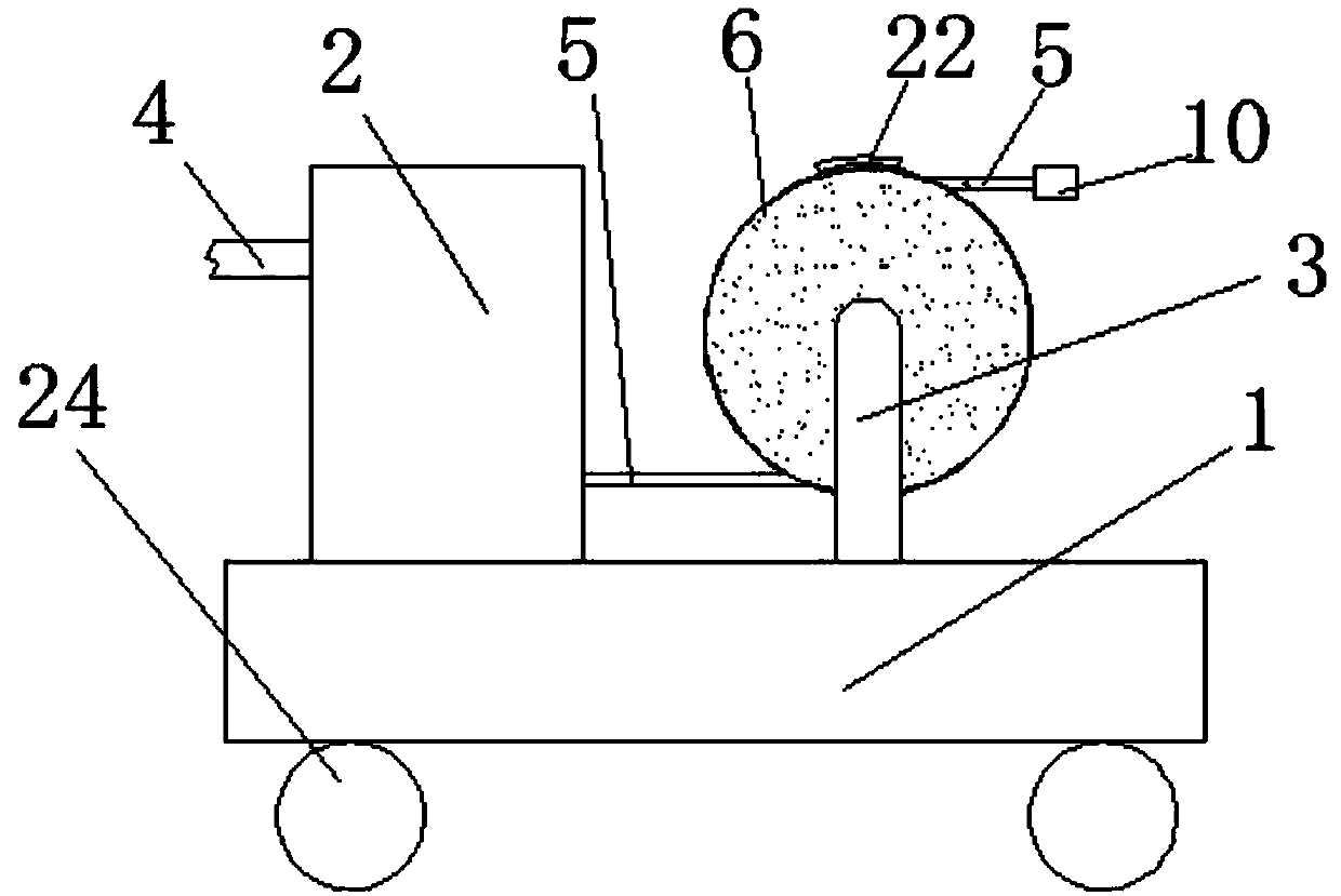
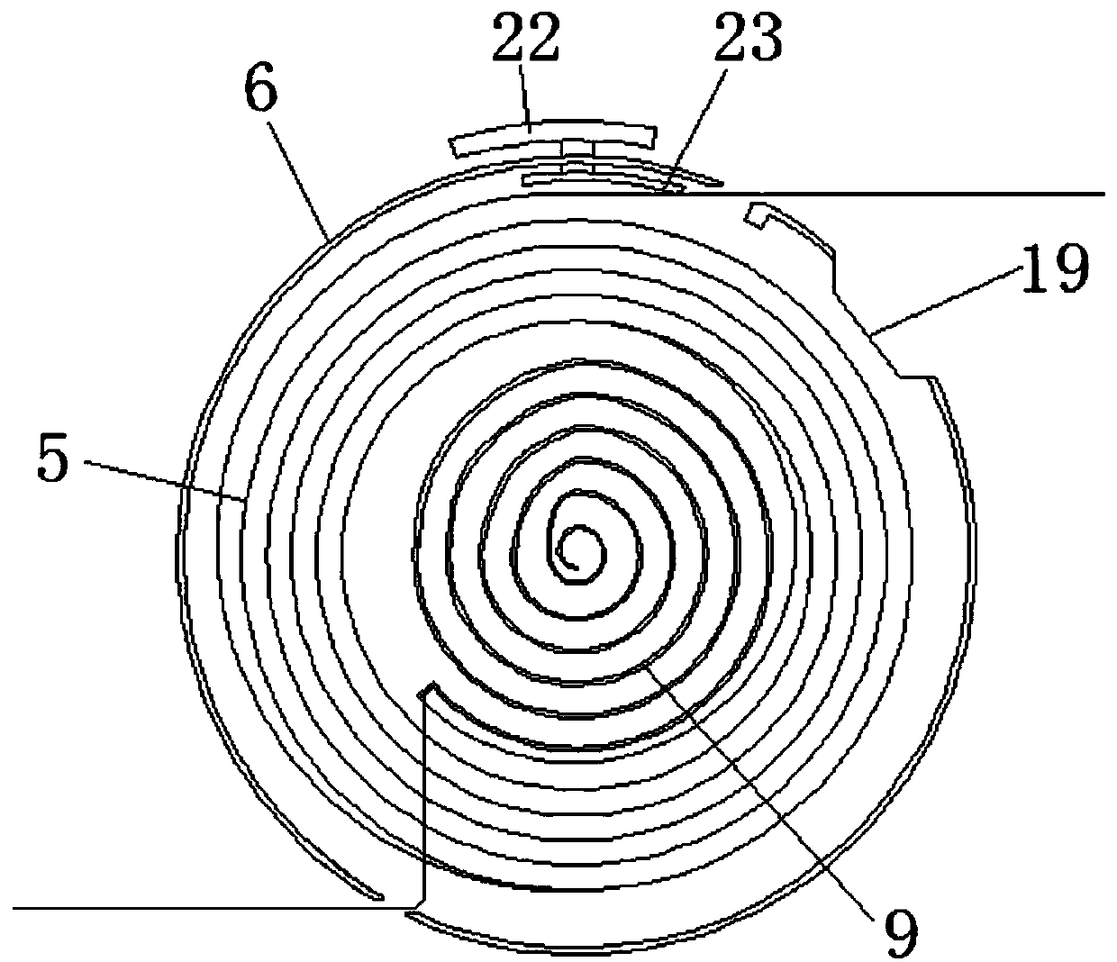
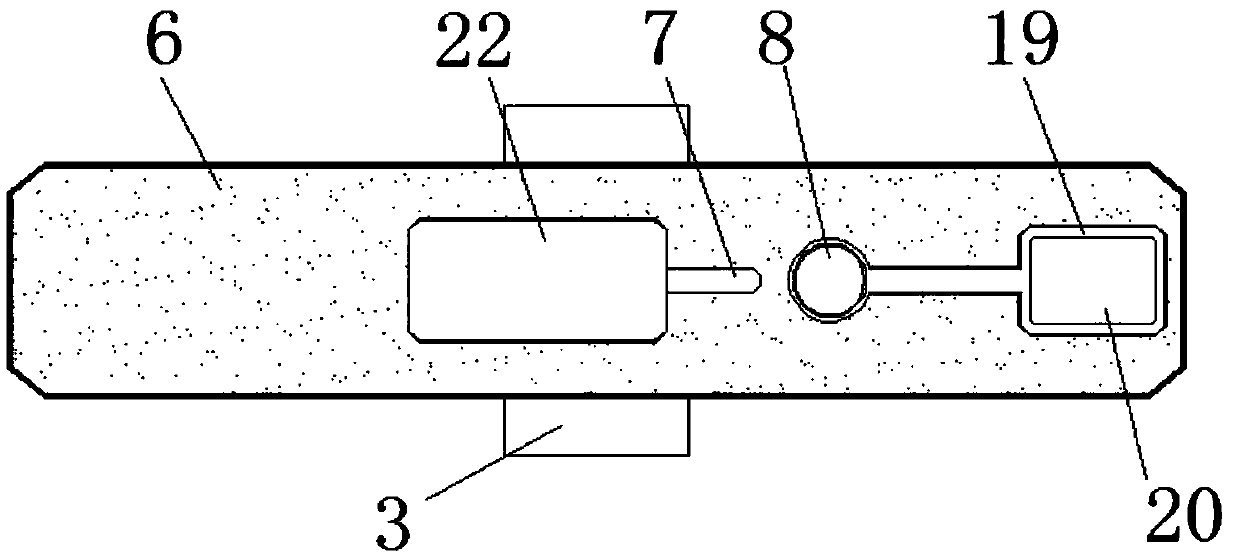
The invention discloses a cleaning device for drainage pipes, which comprises a car body. The upper surface of the car body is provided with a water pump and two symmetrical support columns in sequence. One side of the water pump is connected with a water inlet pipe through a water inlet, and the water pump is far away from the water inlet pipe. One side of the water outlet is connected with an outlet pipe, and a storage box is connected between the two supporting columns. A chute is provided on the top of the storage box, a hole is provided on one side of the chute, and a clockwork spring is provided inside the storage box. The outlet pipe passes through the storage box and connects with the clockwork spring. The end of the outlet pipe far away from the water pump is connected to a flushing device through a hole in the storage box. A waterproof motor is installed in the flushing device, and the output shaft of the waterproof motor is connected to a drive through a coupling. Rod, drive rod is keyed with drive gear at one end away from waterproof motor. The invention is convenient to use, efficiently cleans the drainpipe and greatly reduces the labor load during the arrangement of the waterpipe.

Description

technical field [0001] The invention relates to the technical field of cleaning, in particular to a cleaning device for drainage pipes. Background technique [0002] With the construction of urbanization in our country, the number of urban buildings is also slowly increasing, but every time it rains heavily, the drainage pipes are often blocked, and the accumulated water cannot be drained and spread up. Therefore, it is necessary to clean the drainage pipes from time to time to prevent other clogged. [0003] Small drainage pipes are difficult to clean by manpower because the pipes are small, and the cost of using large equipment is too expensive, so cleaning is very inconvenient. For small drainage pipes, people often apply high pressure to the water and use high-pressure water flow to flush the blockages in the pipes. To use water pipes, the water pipes must be cleaned before and after use, which is very troublesome. Therefore, there is a need for a pipe cleaning device ...

Claims


Application Information

Patent Timeline
Patent Type & Authority Applications(China)
IPC IPC(8): E03F7/10
CPCE03F7/10
Inventor 孙建军
Owner 孙建军
Why Eureka
Try Eureka