Rotation angle detector
A technology of rotation angle and detector, applied in the direction of converting sensor output, instrument, measuring device, etc., can solve the problem of increasing chip size and so on
- Summary
- Abstract
- Description
- Claims
- Application Information
AI Technical Summary
Problems solved by technology
Method used
Image
Examples
no. 1 example
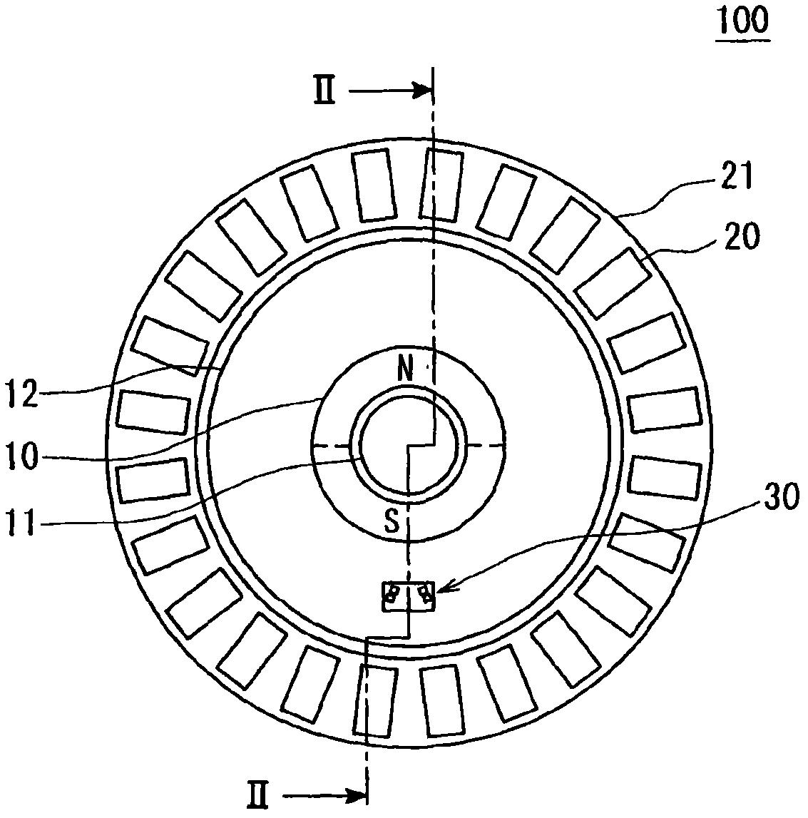
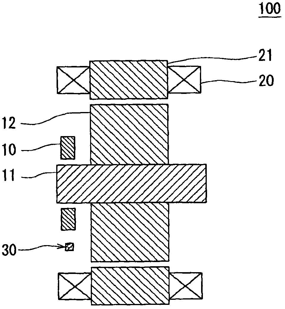
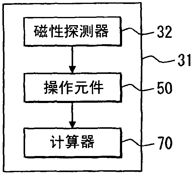
[0027] figure 1 A plan view of the rotation angle detector according to the first embodiment is shown. figure 2 shows along the figure 1 Cross-sectional view of the detector taken by line II-II. image 3 The electrical connections between the magnetic field detection element, the operating element and the calculator are shown. Figure 4 A plan view showing the relationship between the sensor chip and the magnet rotor. The rotation direction of the magnet rotor 10 is defined as the rotation direction. A direction along the thickness of the semiconductor substrate 31 is defined as a thickness direction. A direction perpendicular to the thickness direction and the rotation direction and passing through the magnet rotor center O is defined as a normal direction.
[0028] The probe 100 mainly includes a magnet rotor 10 , a sensor chip 30 , an operating element 50 and a calculator 70 . Such as figure 1 with 2 As shown, a winding 20 for generating a magnetic field surrounds th...
PUM
 Abstract
Description
Claims
Application Information
 - R&D
- Intellectual Property
- Life Sciences
- Materials
- Tech Scout
- Unparalleled Data Quality
- Higher Quality Content
- 60% Fewer Hallucinations
Browse by: Latest US Patents, China's latest patents, Technical Efficacy Thesaurus, Application Domain, Technology Topic, Popular Technical Reports.
© 2025 PatSnap. All rights reserved.Legal|Privacy policy|Modern Slavery Act Transparency Statement|Sitemap|About US| Contact US: help@patsnap.com


