Load-variable loading test device and method for detecting load by using same

A technology of loading test device and variable load, which is applied in the directions of ground installation, transportation and packaging, aircraft component testing, etc., which can solve the problems of the nose landing gear system protrusion performance not being involved in the nose landing gear system protrusion test.

Active Publication Date: 2013-08-21
NANJING UNIV OF AERONAUTICS & ASTRONAUTICS
View PDF4 Cites 3 Cited by
  • Summary
  • Abstract
  • Description
  • Claims
  • Application Information

AI Technical Summary

Problems solved by technology

[0003] Many scholars at home and abroad have conducted systematic and in-depth research on the dynamic characteristics of the nose landing gear system, but there is no research on how to test the nose landing gear system protrusion performance and how to conduct the nose landing gear system protrusion test.

Method used


Image

  • Load-variable loading test device and method for detecting load by using same
  • Load-variable loading test device and method for detecting load by using same
  • Load-variable loading test device and method for detecting load by using same

Examples


Embodiment 1

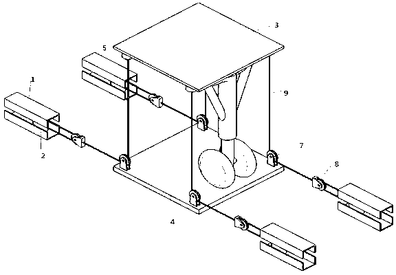
[0025] like figure 1 As shown, the variable load loading test device of the present invention includes a top plate 3, a bottom plate 4, a hydraulic actuator 2 and a friction slide rail 1, and the friction slide rail 1 includes an upper slide rail and a lower slide rail, and the hydraulic actuator cylinder 2 Located between the upper slide rail and the lower slide rail, it also includes four pulley devices that make the top plate 3 move vertically relative to the bottom plate 4, and each pulley device includes bottom plate pulleys fixed on the four corners of the bottom plate 4 7. The top plate 3 and the bottom plate 4 are the same square, the four top corners of the top plate 3 are respectively provided with load sensors 5, the hydraulic actuator 2 is provided with a steel wire rope, and the steel wire rope goes around the bottom plate pulley 7 is connected with load sensor 5.

Embodiment 2

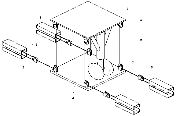
[0027] like figure 2 As shown, the variable load loading test device of the present invention includes a top plate 3, a bottom plate 4, a hydraulic actuator 2 and a friction slide rail 1, and the friction slide rail 1 includes an upper slide rail and a lower slide rail, and the hydraulic actuator cylinder 2 Located between the upper slide rail and the lower slide rail, it also includes four pulley devices that make the top plate 3 move vertically relative to the bottom plate 4. The top plate 3 and the bottom plate 4 are the same square, and the four pulleys of the top plate 3 Load sensors 5 are respectively arranged on each of the top corners, and each pulley device includes a bottom plate pulley 7 fixed on the four top corners of the bottom plate 4 and a movable pulley 8 between the friction slide rail 1 and the bottom plate 4. The moving cylinder 2 is provided with a steel wire rope, and the steel wire rope is connected to the load sensor 5 around the floor pulley 7 and the...

Embodiment 3

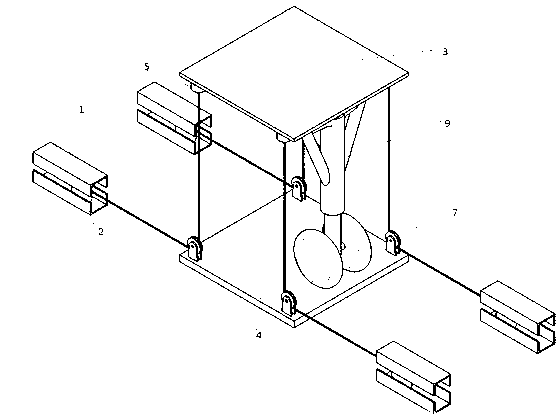
[0029] like image 3 As shown, the variable load loading test device of the present invention includes a top plate 3, a bottom plate 4, a hydraulic actuator 2 and a friction slide rail 1, and the friction slide rail 1 includes an upper slide rail and a lower slide rail, and the hydraulic actuator cylinder 2 Located between the upper slide rail and the lower slide rail, the top plate 3 and the bottom plate 4 are the same square, and the four top corners of the top plate 3 are respectively provided with load sensors 5, and the top plate 3 is opposite to the bottom plate 4. Four pulley devices that move vertically, each pulley device includes bottom plate pulleys 7 fixed on the four corners of the bottom plate 4, top plate pulleys 6 arranged below the load sensor 5 and friction slide rails 1 and the bottom plate The movable pulley between 4, the hydraulic cylinder 2 is provided with a steel wire rope, and the steel wire rope goes around the movable pulley 8, the bottom plate pull...


PUM


Abstract

The invention discloses a load-variable loading test device and a method for detecting a load by using the same. The device comprises a top plate, a bottom plate, a hydraulic actuating cylinder, a friction slide rail and n pulley devices, wherein the friction slide rail is fixed on the ground; the hydraulic actuating cylinder is arranged in the friction slide rail; the n pulley devices make the top plate do vertical lifting motion relative to the bottom plate; n is more than or equal to 2 and is an even number; one end of each pulley device is connected with the hydraulic actuating cylinder, and the other end of each pulley device is connected with the top plate; a load sensor is arranged at the joint of each pulley device and the top plate; and the top plate is provided with a hinge holefor fixing an undercarriage. The actual loaded process of the undercarriage is simulated by load-variable loading, so that whether the undercarriage can protrude to a stipulated height in stipulated time or not is checked.

Description

technical field [0001] The present invention relates to a protruding dynamic test device, more specifically a variable load loading test device, and simultaneously the invention also relates to a method for detecting variable load. Background technique [0002] When the carrier-based aircraft ejects and takes off to the end of the ejection power stroke, the ejection shuttle is separated from the ejection lever, and the front landing gear buffer is rapidly extended by virtue of its own storage or the elastic potential energy input instantaneously from the outside, increasing the angle of attack and pitch of the aircraft in a very short time Speed, so as to achieve the purpose of quickly increasing the lift of the aircraft and making the aircraft leave the ship safely. [0003] Many scholars at home and abroad have conducted systematic and in-depth research on the dynamic characteristics of the nose landing gear system, but the research on how to test the nose landing gear sys...

Claims


Application Information

Patent Timeline
Patent Type & Authority Patents(China)
IPC IPC(8): B64F5/00B64F5/60
Inventor 聂宏于浩魏小辉张明
Owner NANJING UNIV OF AERONAUTICS & ASTRONAUTICS
Why Eureka
Try Eureka