Automatic oil charging and discharging device of diaphragm pump

A technology of oil discharge device and diaphragm pump, which is applied in the direction of pumps, machines/engines, pumps with flexible working elements, etc., which can solve the problems of automatic discharge and achieve low cost, high reliability and safe use

Active Publication Date: 2014-11-05
重庆水泵厂有限责任公司
View PDF7 Cites 0 Cited by
  • Summary
  • Abstract
  • Description
  • Claims
  • Application Information

AI Technical Summary

Problems solved by technology

The device is simple in structure and low in cost, but it cannot be automatically discharged when there is too much oil, which has inherent shortcomings

Method used


Image

  • Automatic oil charging and discharging device of diaphragm pump
  • Automatic oil charging and discharging device of diaphragm pump
  • Automatic oil charging and discharging device of diaphragm pump

Examples


Embodiment Construction

[0017] The present invention will be described in further detail below in conjunction with specific embodiments.

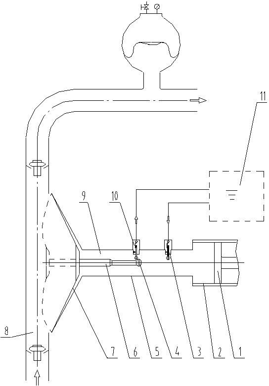
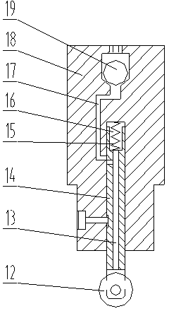
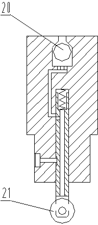
[0018] like figure 1 , figure 2 and image 3 As shown, the automatic oil replenishment and discharge device of the diaphragm pump of the present invention includes a piston cylinder 2 and a piston 1 installed in the piston cylinder 2, and the bottom of the piston cylinder 2 is connected to and communicated with one end of a hydraulic tube 5, and the hydraulic tube 5 The other end of the pipe is connected to the delivery pipe 8, and the lumen of the hydraulic pipe 5 forms an oil chamber 9. A diaphragm 7 is installed between the delivery pipe 8 and the oil chamber 9 , a guide rod 6 that goes deep into the oil chamber 9 is installed in the middle of the diaphragm 7 , and the other end of the guide rod 6 is a guide rod contact 4 . On the side wall of the hydraulic pipe 5, an oil replenishment valve 3 and an oil discharge valve 10 are installed. The connection lin...


PUM


Abstract

The invention discloses an automatic oil charging and discharging device of a diaphragm pump, comprising a piston cylinder and a piston arranged in the piston cylinder, wherein a pipe cavity of a hydraulic pipe forms an oil cavity; a diaphragm is arranged between a delivery pipeline and the oil cavity; the middle part of the diaphragm is connected with one end of a guide rod; the other end of the guide rod is a guide rod contact; an oil charging valve and an oil discharging valve are arranged on the side wall of the hydraulic pipe and are respectively connected with an oil station; the oil charging valve and the oil discharging valve respectively comprise a valve body; each valve body is internally provided with a containing cavity; the containing cavity is internally provided with a return spring and a sliding valve rod matched with the containing cavity in a sliding manner; one end of the return spring is fixed at the bottom part of the containing cavity, and the other end of the return spring is connected with one end of the sliding valve rod; the other end of the sliding valve rod is sliding valve rod contacts which penetrate out of the containing cavity and enters the oil cavity; the guide rod contact is positioned between the sliding valve rod contact of the oil charging valve and the sliding valve rod contact of the oil discharging valve; and the front and rear stroke of the guide rod is controlled, so that the automatic oil charging in oil starvation and automatic oil discharging in more oil are achieved.

Description

Technical field [0001] Background technique [0002] like Figure 4 Oil. [0003] Figure 5 Invention content [0004] [0005] [0006] [0007] [0008] [0009] [0010] Attachment description [0011] figure 1 [0012] figure 2 [0013] image 3 [0014] Figure 4 [0015] Figure 5 Detailed ways [0016] [0017] like figure 1 As well as figure 2 and image 3 [0018] [0019] [0020] [0021] [0022] [0023] [0024] [0025] [0026] [0027]The above -mentioned examples of the present invention are only for examples of the present invention, rather than the limitation of the implementation of the invention.For ordinary technical personnel in their areas, other different forms of changes and changes can be made on the basis of the above description.It is impossible to poverty here.The obvious changes or changes extended by the technical solution belonging to the present invention are still in the scope of the protection of the invention.

Claims


Application Information

Patent Timeline
Patent Type & Authority Patents(China)
IPC IPC(8): F04B43/02
Inventor 管汝光刘祖清张顺平符义红胡未东
Owner 重庆水泵厂有限责任公司
Why Eureka
Try Eureka