
Arrangement method for electrical capacitance tomography (ECT) sensors

A technology of capacitance tomography and layout method, which is applied in the direction of material capacitance, instruments, measuring devices, etc., can solve the problems of lack of test methods, lack of experimental support for theoretical research and development, etc., to improve calculation efficiency, save calculation amount and storage space , the effect of reducing the number of grids

Inactive Publication Date: 2012-02-15
SOUTHEAST UNIV
View PDF4 Cites 8 Cited by
  • Summary
  • Abstract
  • Description
  • Claims
  • Application Information

AI Technical Summary

Problems solved by technology

Since the 1990s, researchers began to study the flow phenomenon of lubricating media in sliding bearings from the perspective of two-phase flow. However, due to the lack of suitable test methods, the development of theoretical research lacks experimental support.

Method used


Image

  • Arrangement method for electrical capacitance tomography (ECT) sensors
  • Arrangement method for electrical capacitance tomography (ECT) sensors
  • Arrangement method for electrical capacitance tomography (ECT) sensors

Examples


Embodiment Construction

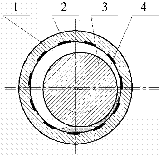
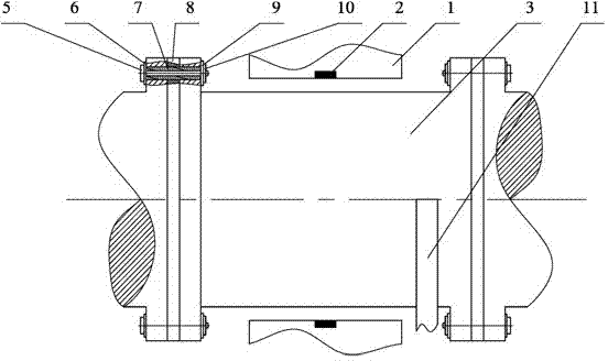
[0037]The number of electrodes of the ECT sensor varies according to the test accuracy requirements. The more electrodes, the higher the test accuracy, but at the same time, the calculation amount is large, and the quick calculation time is long. The fewer electrodes, the smaller the calculation amount, and the lower accuracy. Therefore, the general electrode selection 8 to 16. In this embodiment: the ECT sensor adopts a 12-electrode structure, and the journal section, that is, the rotor 3, is set as one electrode. There is an insulating gasket 8 between the flanges, a fastening bolt insulating gasket 6 is provided between the fastening bolt 5 and the flange, an insulating sleeve 7 is set on the fastening bolt 5, and the fastening bolt 5 and the The nut 10 is matched, wherein a nut insulating gasket 9 is provided between the nut 10 and the end face of the flange. Fastening bolts 5, fastening bolt insulating gaskets 6, insulating sleeves 7, nut insulating gaskets 9, and nuts 10...


PUM


Abstract

The invention discloses an arrangement method for ECT sensors. According to the method, 7 to 15 bearing shell electrodes are arranged at the interior surface of a bearing shell, and a rotor is used as a central electrode of an ECT system; an imaging area is formed between the external surface of the rotor and the interior surface of the bearing shell by utilizing the bearing shell electrodes and the central electrode. Compared to the prior art, the invention has the following advantages: since the imaging area is an annular area without a rotor area, it is of no need to divide the rotor area into grids when a sensitive field is calculated, which enables the amount of grids to be greatly reduced under the condition of same grid density, thereby reducing computational complexity, saving storage space and improving computational efficiency; on the basis of substantially reduced amount of grids, grid density in the imaging area can be increased properly so as to enhance resolution in the imaging area.

Description

technical field [0001] The present invention relates to a sensor arrangement method for Electrical Capacitance Tomography (ECT for short), in particular to the electrical capacitance tomography technology applied to annular gaps such as sliding bearings. This method optimizes the arrangement method of the sliding bearing ECT sensor, and limits the imaging area to the annular gap formed by the outer surface of the rotor through which the lubricating medium flows and the inner surface of the bearing bush. This method can be extended to the field of ECT two-phase flow testing in the annular gap. Background technique [0002] Sliding bearings are one of the key components in heavy rotating machinery such as gas turbines, steam turbines, and compressors, and their performance directly affects the safe and stable operation of equipment. The basic working principle of the sliding bearing is that the lubricating oil enters the gap between the journal and the bearing bush under the ...

Claims


Application Information

Patent Timeline
IPC IPC(8): G01N27/22G01R27/26
Inventor 郭瑞杨道业傅行军杨建刚许传龙王式民曹浩
Owner SOUTHEAST UNIV
Learn More