Squeezing device and squeezing machine

A pressure cylinder and sleeve technology, which is applied in the field of squeezing devices and squeezing machines, can solve the problems that the squeezing machine cannot work continuously, the discharge procedure is complicated, and the liquid discharge cannot be smooth, etc.

Active Publication Date: 2012-02-22
邢征
View PDF6 Cites 14 Cited by
  • Summary
  • Abstract
  • Description
  • Claims
  • Application Information

AI Technical Summary

Problems solved by technology

Existing presses take out the material after pressing, resulting in the press not being able to work continuously, and after the press has been used for a long time, the squeezed liquid cannot be discharged smoothly, resulting in the liquid content of the material after pressing. high
The discharge procedure of the above-mentioned presses after pressing is relatively complicated, and the moisture content of the materials after pressing is relatively high, so the working efficiency and pressing quality of the existing presses are relatively low

Method used


Image

  • Squeezing device and squeezing machine
  • Squeezing device and squeezing machine
  • Squeezing device and squeezing machine

Examples


Embodiment 1

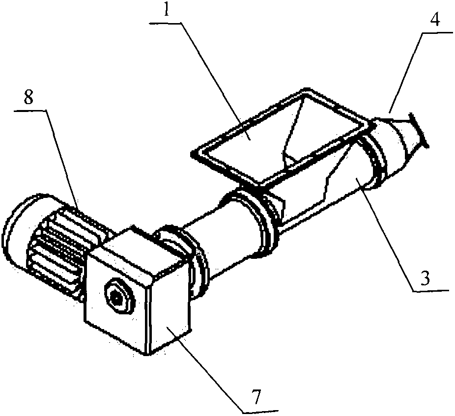
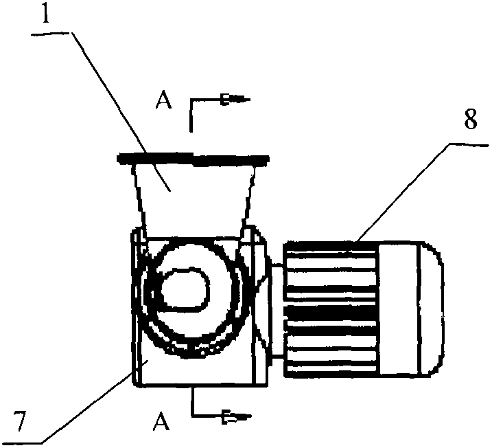
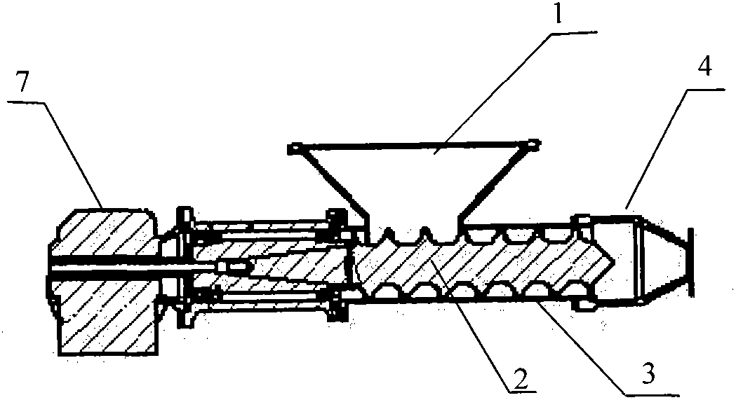
[0030] Such as Figure 1 to Figure 6 As shown, the present invention provides a squeezing device, which includes a feed port 1, a screw 2, a storage sleeve 3, a pressing sleeve 4, a screen cloth 5 and a discharge port 6, such as image 3 As shown, the screw rod 2 is installed in the storage sleeve 3, the upper wall of the storage sleeve 3 is provided with a feed port 1, one end of the storage sleeve 3 is fixed, and the other end is connected to the The pressing sleeve 4 is connected; one end of the screw 2 is connected to the fixed end of the storage sleeve 3, and the other end (which may be called the extrusion end) is suspended in the pressing sleeve 4, The shape of the other end is conical, and the apex angle of the axial section of the conical one end is 90°; as Figure 5 As shown, the pressing sleeve 4 is divided into a pressure cylinder 401 and a taper cylinder 402; a cylindrical screen 5 is installed in the pressure cylinder 401, and the two ends of the screen 5 are co...

Embodiment 2

[0040] The apex angle of the axial section of the conical end of the screw 2 is 90°, the shape of the tapered cylinder is a truncated cone, and the angle a between the two generatrixes of the axial section of the truncated cone is 40°. Other specific implementations are the same as in Example 1.

Embodiment 3

[0042] The apex angle of the axial section of the conical end of the screw 2 is 80°, the shape of the tapered cylinder is a truncated cone, and the angle a between the two generatrixes of the axial section of the truncated cone is 20°. Other specific implementations are the same as in Example 1.


PUM


Abstract

The invention relates to mechanical equipment, in particular to a squeezing device and a squeezing machine. The invention provides the squeezing device, which comprises a feed inlet, a screw, a material storage sleeve, a pressure cylinder and a taper cylinder, a screen and a discharge hole, wherein the screw is arranged in the material storage sleeve; the feed inlet is formed in the sleeve wall on the upper part of the material storage sleeve; one end of the material storage sleeve is fixed; and the other end of the material storage sleeve is connected with the pressure cylinder; one end of the screw is connected with the fixed end of the material storage sleeve; and the other end of the screw is suspended in the pressure cylinder; the cylindrical screen is arranged in the pressure cylinder; the two ends of the screen are connected with the material storage sleeve and the taper cylinder respectively; a liquid outlet is formed in the cylinder wall on the lower part of the pressure cylinder; and the discharge hole is formed in the taper cylinder. The invention also provides the squeezing machine, which comprises an electrical motor, a speed reducer, a rack and the squeezing device provided by the invention. By using the squeezing device and the squeezing machine provided by the invention, the squeezing processing of materials can be finished continuously and efficiently.

Description

technical field [0001] The invention relates to a mechanical device, in particular to a squeezing device and a squeezing machine. Background technique [0002] The purpose of pressing is to separate the solid from the liquid in the material, so as to facilitate the processing of the material. Existing presses take out the material after pressing, resulting in the press not being able to work continuously, and after the press has been used for a long time, the squeezed liquid cannot be discharged smoothly, resulting in the liquid content of the material after pressing. high. The discharge procedure of the above-mentioned extruder is relatively complicated after extrusion, and the moisture content of the material after extrusion is relatively high, so the working efficiency and extrusion quality of the existing extruder are relatively low. Contents of the invention [0003] In order to solve the above-mentioned defects in the prior art, the present invention provides a pre...

Claims


Application Information

Patent Timeline
Patent Type & Authority Applications(China)
IPC IPC(8): B30B9/14B30B15/00B30B15/32
Inventor 邢征
Owner 邢征
Why Eureka
Try Eureka