
Traction transformer

A traction transformer and low-voltage technology, which is applied in the field of transformers, can solve the problems of different layout positions, inconsistent short-circuit force of high-voltage two-column coils, and dissimilar impedance of high-voltage coils, etc., so as to improve short-circuit resistance, short-circuit resistance and operation The effect of safety and reliability

Active Publication Date: 2012-02-22
SANBIAN SCI TECH
View PDF7 Cites 3 Cited by
  • Summary
  • Abstract
  • Description
  • Claims
  • Application Information

AI Technical Summary

Problems solved by technology

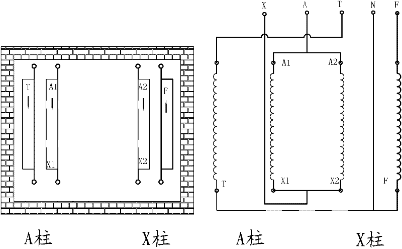
Figure 4 The high-voltage short-circuit currents of the two columns are symmetrical, but the two 1 / 2-column T coils are arranged in different positions, resulting in unequal impedances to the two high-voltage coils. In this way, the short-circuit forces of the high-voltage two-column coils are inconsistent
Therefore, there are certain defects in the anti-short circuit capability and operational safety and reliability of these two kinds of traction transformers

Method used


Image

  • Traction transformer
  • Traction transformer
  • Traction transformer

Examples


Embodiment Construction

[0022] The following are specific embodiments of the present invention and in conjunction with the accompanying drawings, the technical solutions of the present invention are further described, but the present invention is not limited to these embodiments.

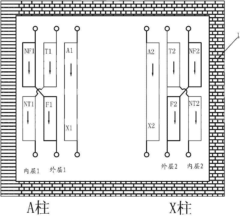
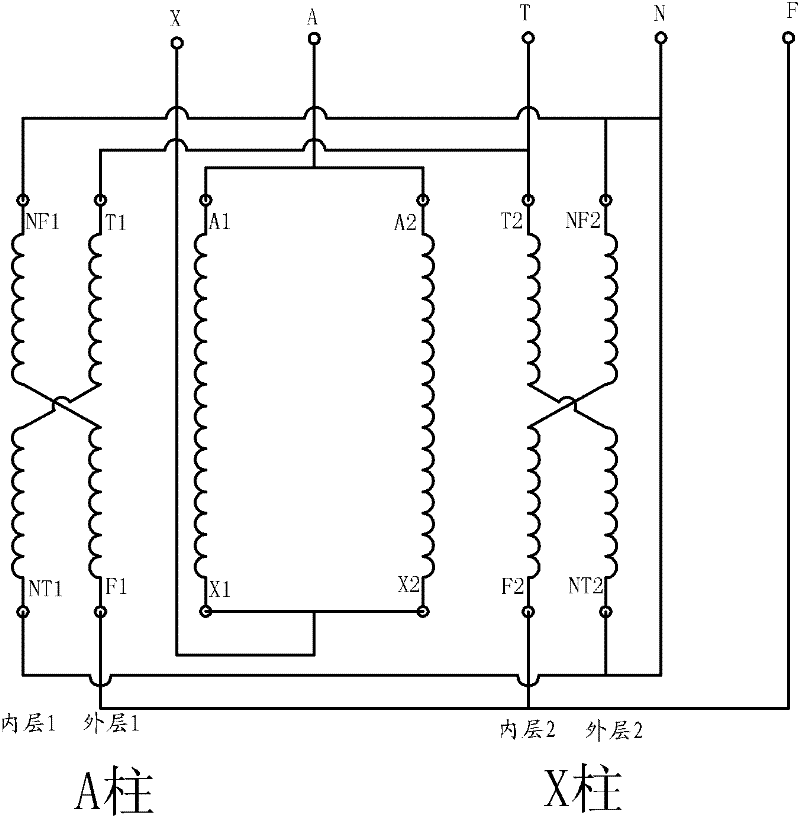
[0023] Such as figure 1 , 2 As shown, the traction transformer includes a single-frame double-column iron core 1 and two high-voltage coils A1-X1 and A2-X2 connected in parallel on the two-column A-column and X-column wound on the core, and the high-voltage wires of the two-column A-column and X-column There are also low-voltage T and F coils in the coils A1-X1 and A2-X2, and the low-voltage T and F coils are respectively divided into four 1 / 4 column T coils T1, NT1, T2, NT2 and four 1 / 4 column F coils F1, NF1, F2, NF2, and the coil turns on each 1 / 4 column are the same, four 1 / 4 column T coils T1, NT1, T2, NT2 and four 1 / 4 column F coils F1, NF1, F2 , NF2 are evenly distributed in the two-column high-voltage coils A1-X...


PUM


Abstract

The invention discloses a traction transformer, belongs to the technical field of transformers, and solves the problems of low short-circuit resistance, running stability and reliability and the like in the prior art. The traction transformer comprises a single-frame double-column iron core and two columns of high tension coils which are connected in parallel and wound on the iron core; low tension coils T and F are also arranged in the two columns of high tension coils; the low tension coils T and F comprise four one-fourth-column coils T and four one-fourth-column coils F respectively, the coil turns of each one-fourth column are the same, the four one-fourth-column coils T and the four one-fourth-column coils F are averagely distributed in two columns of high tension coils and are symmetrical to each other, the low tension coils of the same name in the same column of the high tension coil are connected in series, and the low tension coils of the same name, which are connected in series, in the two columns of the high tension coils are connected in parallel; and the low tension coil T and the low tension coil F which have a parallel structure are connected in series. The traction transformer can effectively improve short-circuit resistance capacity, and improve running safety reliability.

Description

technical field [0001] The invention belongs to the technical field of transformers and relates to a traction transformer. Background technique [0002] With the vigorous development of my country's high-speed railway construction, the demand for railway traction transformers is increasing day by day. Manufacturers in the power manufacturing industry have developed various types of traction transformers that are suitable for the majority of railway users, especially now that a large number of AT power supply methods are used. In this power supply mode, two single-phase traction transformers are connected to V to supply power to the locomotive. [0003] This kind of transformer has two structures, the first one is as image 3 As shown, the structure is that the iron core adopts a single-frame double-column type. The high-voltage coil is divided into two columns, A and X, and the two-column high-voltage coils are connected in parallel. A and X are the lead wires of the high-vol...

Claims


Application Information

Patent Timeline
Patent Type & Authority Applications(China)
IPC IPC(8): H01F27/28H01F27/30H01F27/32
Inventor 徐秋元
Owner SANBIAN SCI TECH
Learn More