Direct-current relay capable of resisting short circuit current and extinguishing arc

A DC relay, anti-short-circuit technology, applied in circuits, electrical switches, electrical components, etc., can solve problems such as the failure of bounce and arcing, the inability of dynamic and static contacts to contact and close reliably, and achieve strong short-circuit resistance and improve short-circuit resistance. Effect

Pending Publication Date: 2020-05-01
XIAMEN HONGFA ELECTRIC POWER CONTROLS
View PDF0 Cites 8 Cited by
  • Summary
  • Abstract
  • Description
  • Claims
  • Application Information

AI Technical Summary

Problems solved by technology

[0003] On the other hand, the high-voltage DC relays with direct-acting magnetic circuit structure in the prior art usually use magnetic blowout to extinguish the arc, that is, a magnetic steel is arranged around the contact point of the two moving and static contacts, and the magnetic field formed by the magnetic steel is used to realize magnetic switching. Blowing out the arc, although the magnetic blowing out the arc is beneficial to the arc extinguishing of the relay and improving the life capacity, but it will also cause a problem that the energized moving reed will be subjected to the Lorentz force under the magnetic field of the magnetic blowing out the arc, due to the magnetic blowing out the arc The layout of the magnetic circuit will cause the Lorentz force on the moving reed to be downward under the magnetic blowout magnetic field, so that the force on the moving reed is the resultant force of electric repulsion + Lorentz force. Once the resultant force > overtravel Contact pressure, then the dynamic and static contacts (moving and static contacts) will not be able to contact and close reliably, resulting in failure to bounce and arc

Method used


Image

  • Direct-current relay capable of resisting short circuit current and extinguishing arc
  • Direct-current relay capable of resisting short circuit current and extinguishing arc
  • Direct-current relay capable of resisting short circuit current and extinguishing arc

Examples


Embodiment 1

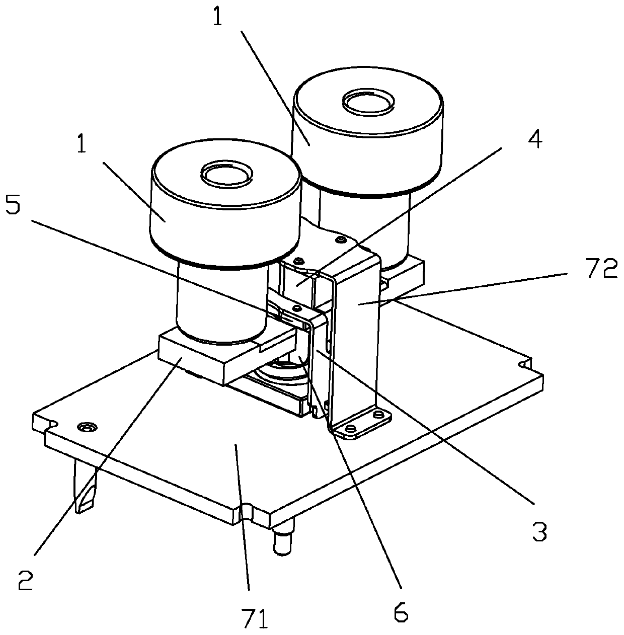
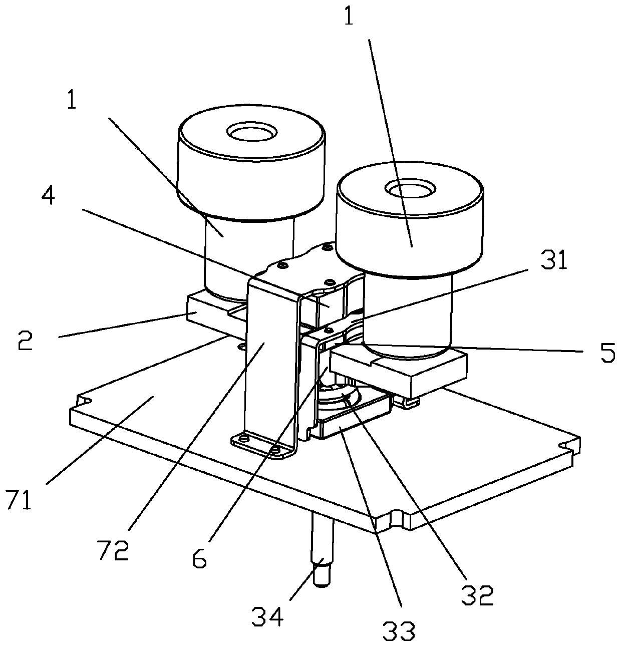
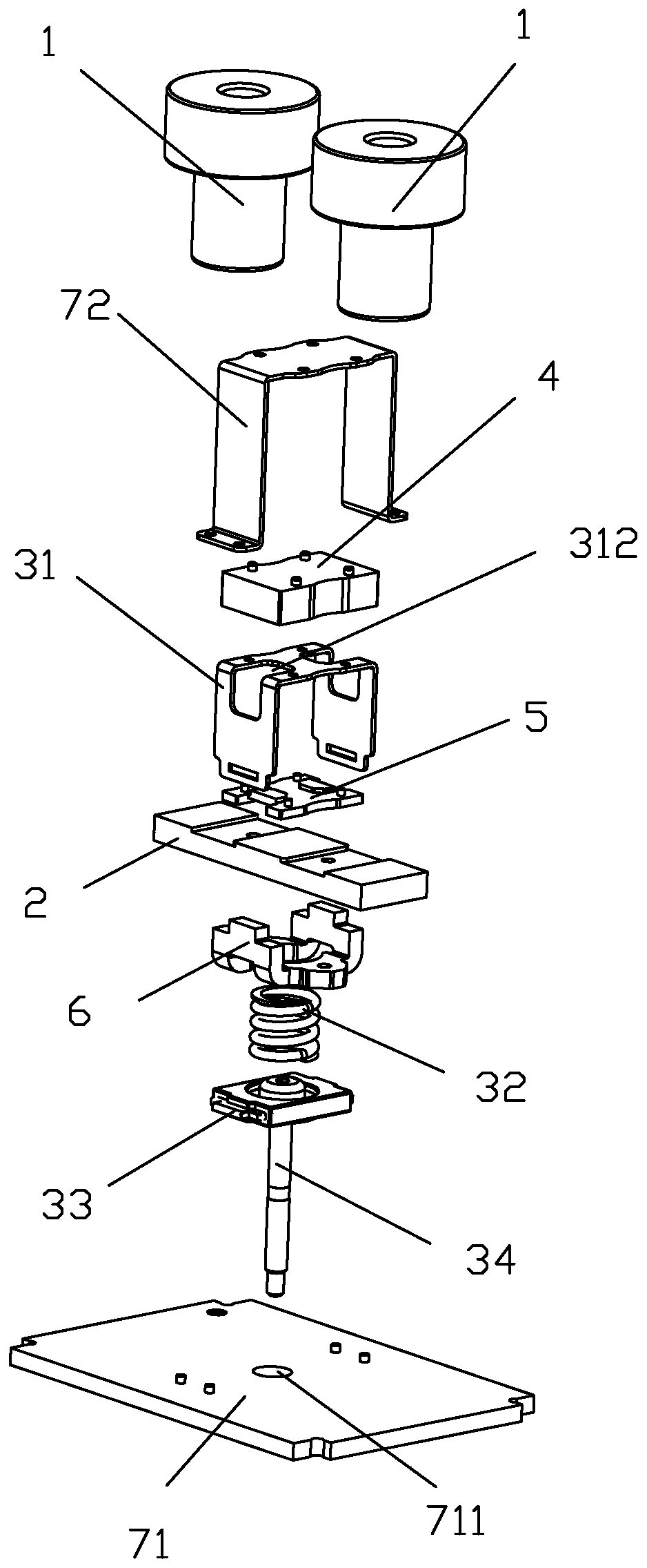
[0050] see Figure 1 to Figure 11 As shown, a DC relay capable of resisting short-circuit current and arc extinguishing of the present invention includes two static contact terminals 1, a straight-type moving reed 2 and a push rod part 3; the moving reed 2 is installed in the push rod part 3, so that under the action of the push rod part 3, the moving contacts at the two ends of the moving reed 2 are matched with the static contacts at the bottom of the two static contact lead-out ends 1; in this embodiment, the moving The two ends of the reed 2 constitute the moving contact of the moving reed 2, and the bottom end of the static contact lead-out 1 constitutes the static contact of the static contact lead-out 1; the DC relay also includes a fixed upper Yoke 4, a follow-up upper yoke 5 and a lower armature 6; the fixed upper yoke 4 is fixed above the push rod part 3 corresponding to the position between the two moving contacts of the moving reed 2 , the follow-up upper yoke 5 i...

Embodiment 2

[0062] see Figure 11 to Figure 16 As shown, a kind of arc extinguishing and anti-short circuit current DC relay of the present invention is different from Embodiment 1 in that a magnetic steel 81 for arc extinguishing is also arranged beside the contacts; The magnetic steel 81 is two pieces, and the two magnetic steels 81 are respectively configured at the positions corresponding to the dynamic and static contacts outside the two ends of the length of the moving reed 2, and the magnetic poles on the opposite sides of the two magnetic steels 81 are set for the opposite.

[0063] In this embodiment, the DC relay also includes two U-shaped yoke clips 82, the U-shaped bottom walls of the two yoke clips 82 are respectively connected to the opposite sides of the two magnets 81, and the two yoke clips 82 The ends of the two side walls of the U-shape respectively exceed the relative positions of the corresponding movable and static contacts and are close to each other at the middle po...

Embodiment 3

[0066] see Figure 17 to Figure 21 As shown, a kind of arc extinguishing and anti-short-circuit current DC relay of the present invention is different from Embodiment 1 in that a magnetic steel 91 for arc extinguishing is also arranged beside the contacts; There are three magnetic steels 91, two of which are respectively arranged on the outer sides of the width of the movable reed 2, and are in a position corresponding to one of the dynamic and static contacts (right side) in the three magnetic steels 91. , and the magnetic poles of the two magnetic steels 91 facing the moving and static contacts are set to be the same; the other magnetic steel 91 in the three magnetic steels 91 is arranged on the outside of one side of the length of the moving reed, And it is in the position corresponding to another moving and static contact (left side), and the pole face of said another piece of magnet steel 91 (left side) is substantially perpendicular to the pole faces of said two pieces o...


PUM


Abstract

The invention discloses a direct-current relay capable of resisting short circuit current and extinguishing arc. The direct-current relay comprises two static contact leading-out ends, a straight sheet type movable contact spring and a push rod part, , and further comprises a fixed upper yoke, a follow-up upper yoke and a lower armature. The fixed upper yoke is fixed above the push rod part corresponding to the position between the two movable contacts of the movable contact spring, the follow-up upper yoke is fixed in the push rod part corresponding to the position above the movable contact spring, and the lower armature is fixed on the bottom end surface of the movable contact spring corresponding to the position; the fixed upper yoke, the follow-up upper yoke and the lower armature arerespectively distributed along the width of the movable contact spring, and two magnetic conductive rings are formed on the width of the movable contact spring. The electromagnetic attraction force can be increased, so that the short circuit resistance of the product is greatly improved, and the short circuit resistance current reaches the level of 16 kA.

Description

technical field [0001] The invention relates to the technical field of relays, in particular to a DC relay capable of resisting short-circuit current and extinguishing arcs. Background technique [0002] The anti-short-circuit capability of DC relays is a relatively difficult indicator at present. At present, the anti-short-circuit current of high-voltage DC relays has reached the level of 16kA. When the short-circuit current passes through the movable and static contacts, the electric repulsion generated between the movable and static contacts will cause the contacts to repel, which will eventually lead to severe arcing and make the relay invalid. The root of solving short-circuit resistance is to ensure that the contacts are in reliable contact without bouncing off. In the prior art, a short-circuit current-resistant magnetic ring composed of an upper yoke and a lower armature is usually added to the moving reed. When the short-circuit current flows through the moving ree...

Claims


Application Information

Patent Timeline
Patent Type & Authority Applications(China)
IPC IPC(8): H01H9/02H01H9/30
CPCH01H50/18H01H50/36H01H50/56H01H50/58H01H9/44
Inventor 钟叔明代文广王萌
Owner XIAMEN HONGFA ELECTRIC POWER CONTROLS
Why Eureka
Try Eureka