
Torque sensor

A torque sensor and torque technology, applied in the field of torque sensors, can solve the problems of reduced measurement sensitivity, large axial thickness, damage to measurement accuracy, etc., and achieve improved measurement accuracy, high bending stiffness and axial stiffness, and high measurement speed. Effect

Inactive Publication Date: 2012-02-22
HOTTINGER BALDWIN MESSTECHNIK GMBH
View PDF8 Cites 10 Cited by
  • Summary
  • Abstract
  • Description
  • Claims
  • Application Information

AI Technical Summary

Problems solved by technology

Since the total torque has to be transmitted through the annular measuring body part, its axial thickness is relatively large, thereby reducing the measurement sensitivity
At the same time, the uniform ring-shaped measuring body part also transmits interfering bending stresses or other parasitic forces, which can additionally impair the measuring accuracy

Method used


Image

  • Torque sensor
  • Torque sensor
  • Torque sensor

Examples


Embodiment Construction

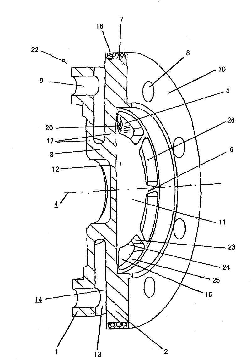
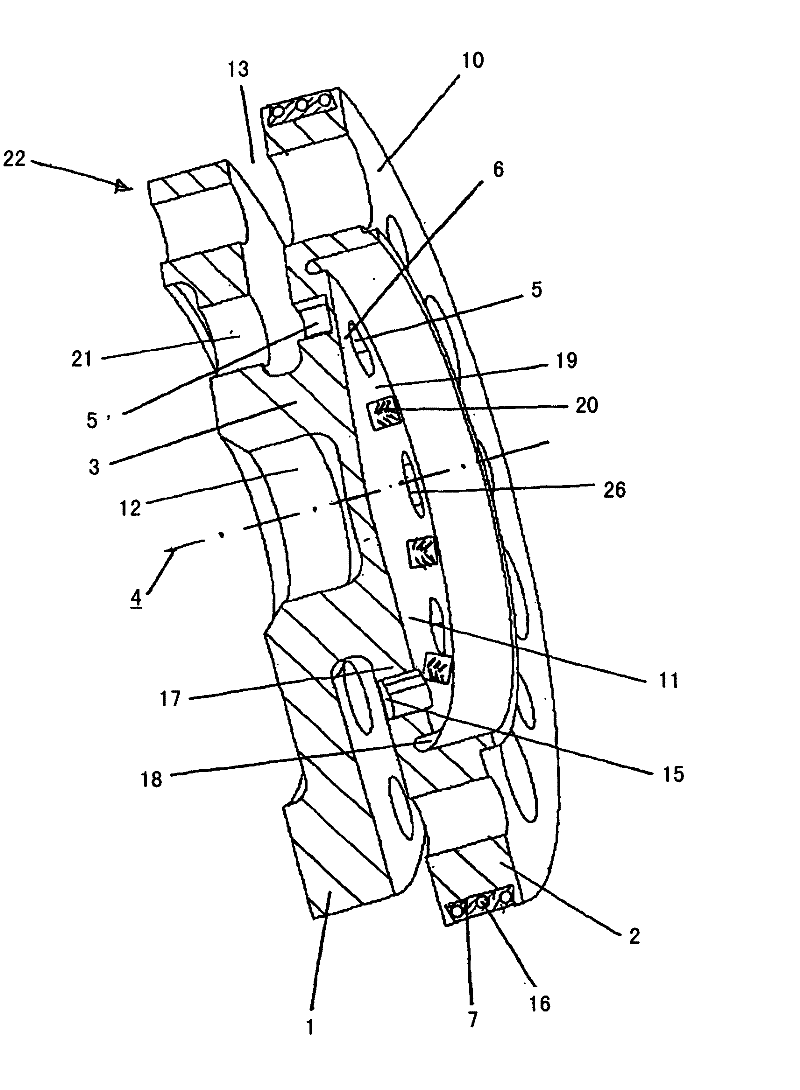
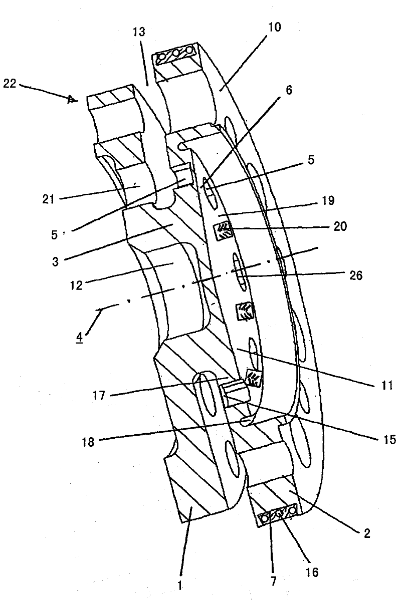
[0020] in the attached figure 1 shows a single-sided torque sensor in a sectional view, which comprises two rotationally symmetrical and axially opposite disk-shaped mounting flanges 1, 2, which are rigidly connected to each other via an annular torque transmission element 3, In this case, preferably eight measuring pockets 5 in the form of notches 5 are arranged radially and equally spaced relative to the axis of rotation 4 on the outwardly directed disk surface of the fastening flange designed as measuring flange 2 , at the sides of which Strain gauges 20 are applied to the base 15 as shear loads, the measuring pockets 5 being separated from each other by eight radial reinforcement webs 6 .

[0021] The torque sensor shown is set up for measuring torque between two shafts with a nominal speed of up to about 25000 revolutions per minute - or a nominal torque of up to 1 kNm between machine parts, wherein such a torque sensor is also Available for nominal torques from 100Nm to...


PUM

PropertyMeasurementUnit
diameteraaaaaaaaaa
diameteraaaaaaaaaa

Abstract

The invention relates to a torque sensor which consists of two disc-shaped fastening flanges (1, 2) which are opposite and parallel to one another and are connected to one another by means of a radially inner torque transmission element (3). In this case, one fastening flange (2) is designed as a measuring flange which has, between the outer fastening annular surface (10) thereof and the torque transmission element (3), in a coaxially circumferential region, a plurality of recesses (5, 5'), to the outer surfaces (19) or bases (15) of which shear force sensors (20) are applied. The invention is characterized in that the recesses (5, 5') are formed by at least three measuring pockets which are separated from one another by means of at least three radial stiffening webs (6). In this case, the measuring flange (2), in the radially inner region thereof with respect to the radially outer fastening annular surface (10), is in the form of a circumferential closed surface to which the measurement electronics are fastened, which electronics are hermetically sealed with a cover.

Description

technical field [0001] The invention relates to a torque sensor according to the preamble of claim 1 . Background technique [0002] On rotating machines it is often necessary to detect its torque during operation. For this purpose, in particular the torque of the rotating shaft is measured, wherein the torque receiver rotates synchronously with the shaft and thus permanently measures the torque transmitted by the shaft. For this purpose, torque sensors are often used which are equipped with torque measuring discs, which are positioned between the rotating shaft parts and are fastened thereto. For this purpose, the torque receiver often has an annular fastening flange which is screwed to the counterflange of the shaft. In this case, it is often necessary to fasten the torque receiver in relatively short shaft sections or between existing flanges which only provide little axial installation space. In this case, the fastening must be carried out in such a way that as few di...

Claims


Application Information

Patent Timeline
Patent Type & Authority Applications(China)
IPC IPC(8): G01L3/14
CPCG01L3/1457
Inventor W·诺尔德J·安德烈
Owner HOTTINGER BALDWIN MESSTECHNIK GMBH
Features
  • Generate Ideas
  • Intellectual Property
  • Life Sciences
  • Materials
  • Tech Scout
  • Unparalleled Data Quality
  • Higher Quality Content
  • 60% Fewer Hallucinations
Learn More