
Die for punching chamfers

A stamping chamfering and die technology, applied in the field of stamping chamfering die, can solve the problems of uneven chamfering, affecting the appearance quality of products, etc., and achieve high processing efficiency, easy to ensure product dimensional accuracy and shape accuracy, and simple mold debugging. Effect

Active Publication Date: 2012-02-29
隆昌山川机械有限责任公司
View PDF5 Cites 15 Cited by
  • Summary
  • Abstract
  • Description
  • Claims
  • Application Information

AI Technical Summary

Problems solved by technology

[0005] The purpose of the present invention is to provide a die for stamping and chamfering, which solves the technical problem that the chamfering method is easy to cause uneven chamfering and affects the appearance quality of the product, so as to effectively solve the problems in the above-mentioned prior art

Method used


Image

  • Die for punching chamfers
  • Die for punching chamfers
  • Die for punching chamfers

Examples


Embodiment

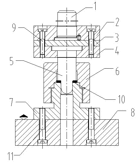
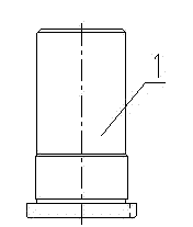
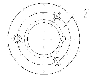
[0032] Such as figure 1 As shown, the mold for stamping chamfering of the present invention comprises a die handle 1, an upper die base 2, an upper backing plate 3, a fixed plate 4, a pressure head 5, a discharge positioning ring 6, a lower die 7 and a lower die base 8, and the Die handle 1 and the hole on the upper die base 2 are interference fit; the upper backing plate 3 is set under the upper die base 2, the fixing plate 4 is set under the upper backing plate 3, and the mold handle 1 passes through the upper die base 2 is in contact with the upper backing plate 3, one end of the upper punch 5 is set in the fixed plate 4, the other end passes through the discharge positioning ring 6 and slides with the lower die 7, and the discharge positioning ring 6 and the lower die 7 There is an annular space gap 10 between them. The lower die 7 is located below the discharge positioning ring 6, the lower die 7 is threadedly connected with the discharge positioning ring 6, the lower di...


PUM


Abstract

The invention discloses a die for punching chamfers. The die comprises a shank, an upper die base, an upper base plate, a fixed plate, a pressing head, a material-discharging positioning ring, a lower die and a lower die base, wherein the shank is in interference fit with a hole in the upper die base; the upper base plate is arranged below the upper die base; the fixed plate is arranged below the upper base plate; the shank passes through the upper die base and contacts the upper base plate; one end of an upper male die is arranged in the fixed plate; the other end of the upper male die passes through the material-discharging positioning ring and is in sliding fit with the lower die; and a circular space gap is formed between the material-discharging positioning ring and the lower die. By the die for punching the chamfers, technical problem that the appearance quality of a product is poor because the chamfers machined by a machining chamfering method are uniform is solved, and compared with the conventional machining chamfering method, the die for punching the chamfers has the advantages that: production efficiency is greatly improved; production cost is reduced; and a phenomenon of nonuniform chamfers caused during processing is avoided; moreover, by adoption of the die, no scrap iron is generated, the processing efficiency is high, labor intensity is low and mass production can be realized.

Description

technical field [0001] The invention relates to a die for stamping and chamfering, which belongs to the technical field of dies. [0002] Background technique [0003] In stamping products, some parts need to chamfer the holes, such as stamping parts such as gaskets, which require 1x45?? chamfering of the inner hole, and the method of machine chamfering is often used. For example, a limit baffle in the outer structure of the automobile shock absorber requires 45° of chamfering at both ends of the inner hole. In traditional processing, this process uses a lathe to chamfer the hole, which is not only inefficient, but also due to the production characteristics of stamping parts, it is not easy to ensure the concentricity of the inner and outer circles. Due to different concentricity, the poured corners are not uniform, and the chamfering is biased, which affects the quality of the product. [0004] Contents of the invention [0005] The purpose of the present invention is...

Claims


Application Information

Patent Timeline
Patent Type & Authority Applications(China)
IPC IPC(8): B21D37/10
Inventor 吴家文胡宏
Owner 隆昌山川机械有限责任公司
Learn More