Test device for performance of overhead line fault indicator

A fault indicator and test device technology, applied in the direction of measuring devices, instruments, measuring electrical variables, etc., can solve problems such as lack of perfect detection equipment and detection methods, achieve high test accuracy and improve test efficiency

Inactive Publication Date: 2012-02-29
NORTH CHINA ELECTRIC POWER UNIV (BAODING)
View PDF4 Cites 20 Cited by
  • Summary
  • Abstract
  • Description
  • Claims
  • Application Information

AI Technical Summary

Problems solved by technology

[0004] At present, there are no perfect testing equipment and scientific testing method

Method used


Image

  • Test device for performance of overhead line fault indicator
  • Test device for performance of overhead line fault indicator
  • Test device for performance of overhead line fault indicator

Examples


Example Embodiment

[0034] Example 1: Short-circuit fault indication test

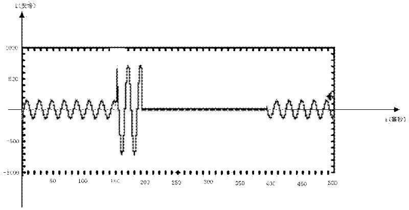
[0035] Fault indicator parameter description: Rated voltage U n =6700V (phase voltage), load current I 1 =50A, working frequency f=50Hz, fixed value of short-circuit current I x =400A, short circuit fault alarm current minimum duration T that can be identified x = 40 milliseconds, the minimum recognition time of reclosing (tripping state duration) T ch = 200 milliseconds. (For other specific indicators, please refer to the Technical Specifications for Distribution Line Fault Indicators promulgated by the State Grid Corporation of China in 2010——Q / GDW 436-2010)

[0036] The tester outputs the following four states:

[0037] 1) Normal operating state:

[0038] The output voltage initial angle θ u = 0; frequency f = 50Hz;

[0039] Output current initial angle θ i =-30°, frequency f=50Hz;

[0040] Duration T 1 = 10 minutes.

[0041] 2) Short circuit fault status:

[0042] The output voltage initial angle θ ...

Example Embodiment

[0057] Example 2: Single-phase ground fault indication test

[0058] Fault indicator parameter description: line voltage U n =6700V (phase voltage), load current I 1 =30A, working frequency f=50Hz, ground fault current fixed value ΔI d =50A, identifiable ground fault current duration ΔT d1 = 40 milliseconds, phase voltage drop ratio ΔU d %=30%, phase voltage drop duration ΔT d2 = 60 seconds. (For other specific indicators, please refer to the Technical Specifications for Distribution Line Fault Indicators promulgated by the State Grid Corporation of China in 2010——Q / GDW 436-2010)

[0059] The tester outputs the following three states:

[0060] 1) Normal operating state:

[0061] The output voltage f=50Hz, θ u = 0;

[0062] Output current f=50Hz, θ i = -30°;

[0063] Duration T 1 = 10 minutes.

[0064] 2) Ground fault state 1:

[0065] Output current i out = 2 I l...


PUM

PropertyMeasurementUnit
Diameteraaaaaaaaaa

Abstract

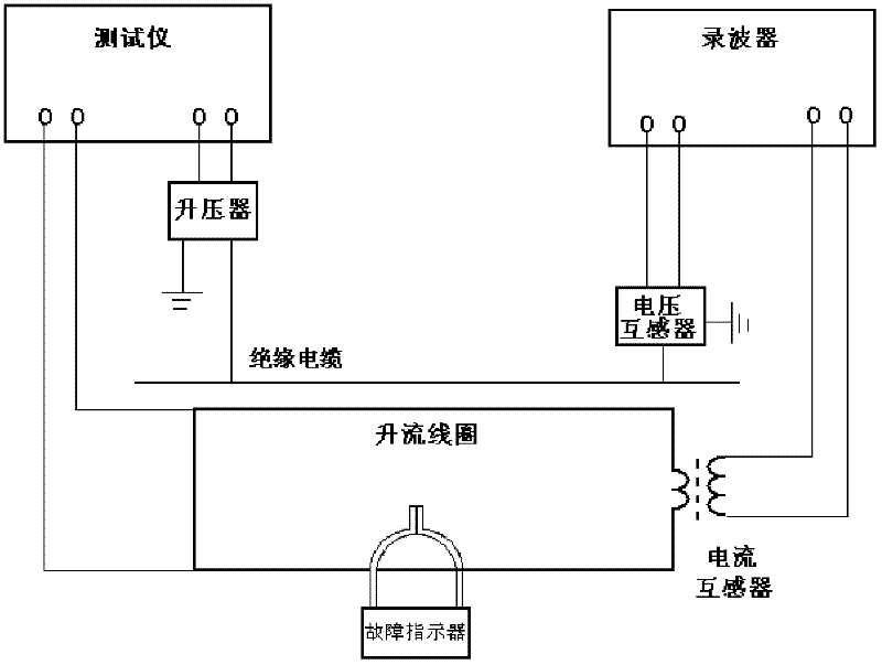
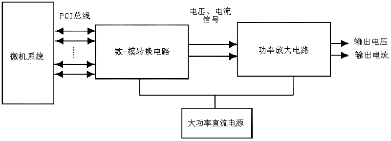
The invention discloses a test device for the performance of an overhead line fault indicator, which belongs to the technical field of the testing of fault indicators. In the test device, a tester is connected with a current boosting coil and a booster respectively; an oscillograph is connected with a voltage transformer and a current transformer respectively; the booster is connected with the voltage transformer by an insulation cable; the current transformer and the current boosting coil are assembled together; overhead line simulation equipment consists of the tester, the current boosting coil, the booster and the insulation cable; the fault indicator is arranged on the current boosting coil; and the booster and the voltage transformer are connected to the ground. In the test device, various states of an overhead line are simulated by the overhead line simulation equipment, and the functions and electric properties of the fault indicator are detected according to related data recorded by the oscillograph. The test device has the advantages that: the test accuracy and test efficiency are improved, and powerful support can be provided for the development of novel fault indicators.

Description

technical field [0001] The invention belongs to the technical field of fault indicator testing, in particular to a test device for the performance of an overhead line type fault indicator. Background technique [0002] The fault indicator is generally installed on the distribution line of the power system to indicate the path of the fault current flow, so as to realize the fault location. [0003] Fault indicators have the characteristics of low price, convenient installation, simple operation and maintenance, etc., and have been popularized and applied in my country's distribution network. [0004] At present, there are no perfect testing equipment and scientific testing methods for the functional and electrical performance tests of overhead line fault indicators. Contents of the invention [0005] The present invention discloses a test device for the performance of an overhead line fault indicator aimed at the above-mentioned defects. Its structure is as follows: the te...

Claims


Application Information

Patent Timeline
IPC IPC(8): G01R35/00
Inventor 王炳革关兴虎
Owner NORTH CHINA ELECTRIC POWER UNIV (BAODING)
Why Eureka
Try Eureka