
Spring mounting tool

A technology for installing tooling and strips, which is applied in the manufacture of tools, hand-held tools, etc., can solve the problems of large return spring force, difficulty in controlling the direction of the installer, work-related injuries or product scrapping, etc., to achieve safety in the installation process, improve control difficulties, The effect of obvious labor-saving effect

Inactive Publication Date: 2012-03-14
江苏瑞安贝医疗器械有限公司
View PDF5 Cites 2 Cited by
  • Summary
  • Abstract
  • Description
  • Claims
  • Application Information

AI Technical Summary

Problems solved by technology

[0002] In the medical device industry, the problem of difficult installation of the return spring of the movable handle for PPH and tubular digestive tract staplers has not been well resolved.
This method has very high requirements on installation skills and proficiency. In addition, the elastic force of the return spring is very large, and it is difficult for the installer to control the direction. Often, the "V"-shaped screwdriver slips off the return spring.
Once it slips during operation, it is easy to stab yourself or the surface of the product, resulting in work-related injuries or product scrapping

Method used


Image

  • Spring mounting tool
  • Spring mounting tool
  • Spring mounting tool

Examples


Embodiment Construction

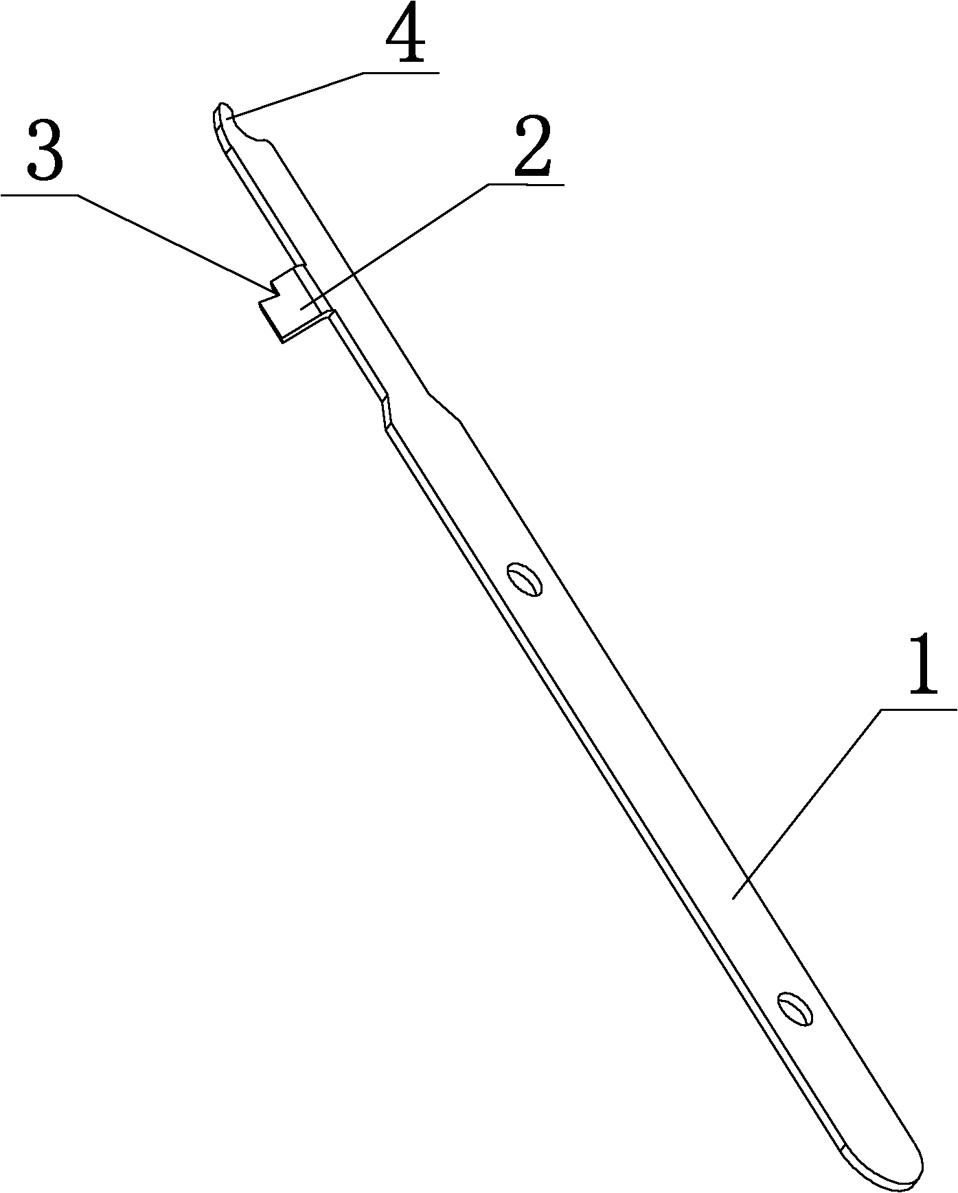
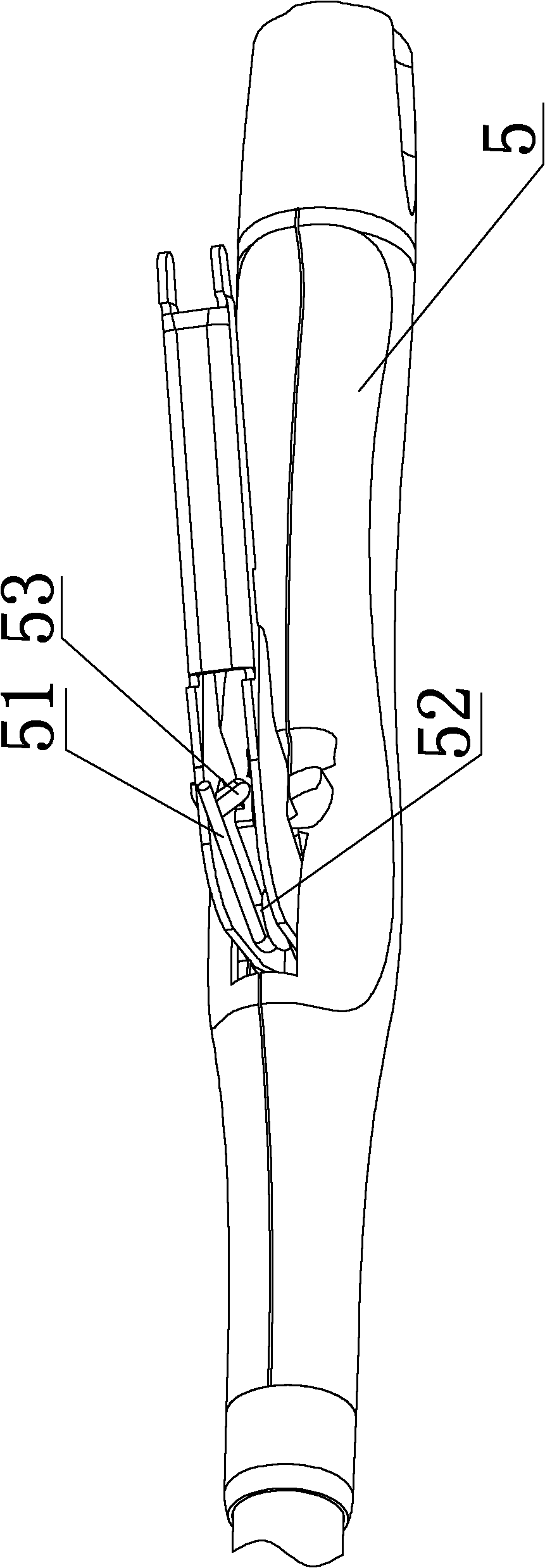
[0014] Such as figure 1 , figure 2 The shown spring installation tool includes a bar-shaped handle 1 with a rectangular cross section. A protrusion 2 is provided on the peripheral surface of the bar-shaped handle 1 , and a "V"-shaped notch 3 is opened on the protrusion 2 . One end of the bar-shaped handle 1 is also provided with a protruding support head 4 along its length direction, and the support head 4 is an arc-shaped head. The notch 3 is arranged on the side of the protrusion 2 facing the support head 4, and the distance between the protrusion 2 and the support head 4 should be less than as image 3 , Figure 4 The distance between the movable handle boss 53 and the return spring pin 52 of the tubular digestive tract stapler shown.

[0015] How to use: first clamp the gap 3 on the bar handle 1 to the free end of the return spring 51 of the tubular digestive tract stapler 5, then compress the return spring 51 so that the support head 4 of the bar handle 1 is against t...


PUM


Abstract

The invention relates to a spring mounting tool, which comprises a strip-type handle, wherein a bulge is arranged on the circumferential surface of the strip-type handle; and a notch is formed in the bulge and is formed on one surface, which faces the top end of the strip-type handle, on the upper side of the bulge. The invention provides a spring mounting tool capable of mounting a restoring spring of a movable handle safely and easily, and the injury of operators or the rejection of products is avoided effectively.

Description

technical field [0001] The invention relates to a tool, in particular to a spring installation tool. Background technique [0002] In the medical device industry, the problem of difficult installation of the return spring of the movable handle of the PPH and tubular digestive tract stapler has not been well resolved. The current commonly used installation method is to grind the "one"-shaped screwdriver into a "V" shape. Then use a "V"-shaped screwdriver to push the free end of the return spring until the free end of the return spring is stuck behind the boss on the movable handle. This method has very high requirements on installation skills and proficiency. In addition, the elastic force of the return spring is very large, and it is difficult for the installer to control the direction. Often, the "V"-shaped screwdriver slips off the return spring. . Once slipping occurs during operation, it is easy to stab yourself or the surface of the product, resulting in work-related...

Claims


Application Information

Patent Timeline
Patent Type & Authority Applications(China)
IPC IPC(8): B25B27/30
Inventor 周亚伟丁自成
Owner 江苏瑞安贝医疗器械有限公司
Learn More