A method of fabricating an exposed optical fiber array with an inclined end face and its substrate

A technology of optical fiber array and inclined end face, which is applied in the field of optical communication, can solve the problems of damage, high labor cost, falling off or breaking, etc., and achieve the effect of reducing material requirements, reducing scrap rate, and reducing requirements

Active Publication Date: 2019-11-08
武汉生一升光电科技有限公司
View PDF7 Cites 0 Cited by
  • Summary
  • Abstract
  • Description
  • Claims
  • Application Information

AI Technical Summary

Problems solved by technology

[0005] However, the method discussed in this patent has the following problems: 1) In the process of rearranging the polished bare optical fiber into a new substrate, it cannot be guaranteed that each optical fiber will not be slightly twisted, especially if the number of optical fibers is greater than 1 Therefore, the reflection surface angle of each bare fiber may be inconsistent; 2) In the process of rearranging the bare fiber, the length of each fiber cannot be guaranteed to be exactly the same, which will cause difficulties in the coupling of some channel fibers; 3) The polished end face of the bare optical fiber that is ground to a certain angle is very fragile, and it is easy to collide and cause damage during the process of re-arranging into the substrate, making it unusable; 4) It needs to arrange the optical fiber twice, the process is complicated, and the labor cost is high; 5) The first The substrate and cover plate after one grinding and polishing cannot be reused, and the material loss is high
[0007] Although the production method provided by the patent with the publication number CN103383482 A avoids the problems encountered in the patent with the publication number CN102520495A, there are still some new problems: 1) The bare optical fiber coated with paraffin is in direct contact with the grinding disc during the grinding process , the gravity of the grinding fixture, the friction of the grinding sand, and uncontrollable external forces are likely to cause the bare fiber part to fall off or break together with the paraffin, resulting in product scrap; The process of paraffin waxing the part is more complicated, and it needs to be very careful to avoid deformation of the bare optical fiber; 3) Paraffin wax with special properties is required, the hardness of the paraffin is too high and brittle, and the toughness of the paraffin is too high and easy to deform, resulting in complicated material technology

Method used


Image

  • A method of fabricating an exposed optical fiber array with an inclined end face and its substrate
  • A method of fabricating an exposed optical fiber array with an inclined end face and its substrate
  • A method of fabricating an exposed optical fiber array with an inclined end face and its substrate

Examples


Embodiment Construction

[0041] The present invention will be further described in detail below in conjunction with the accompanying drawings and specific embodiments.

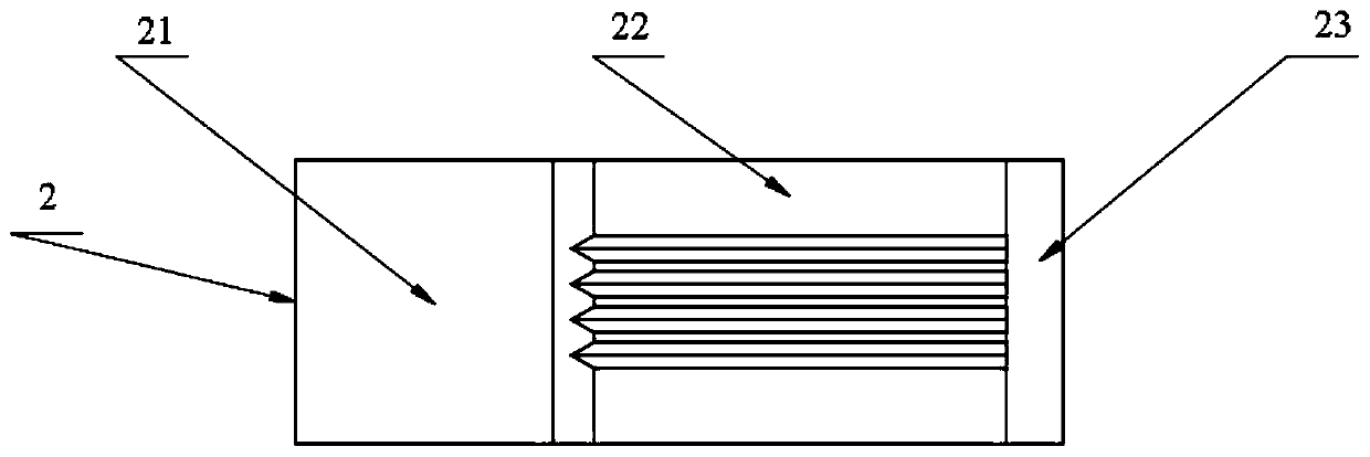
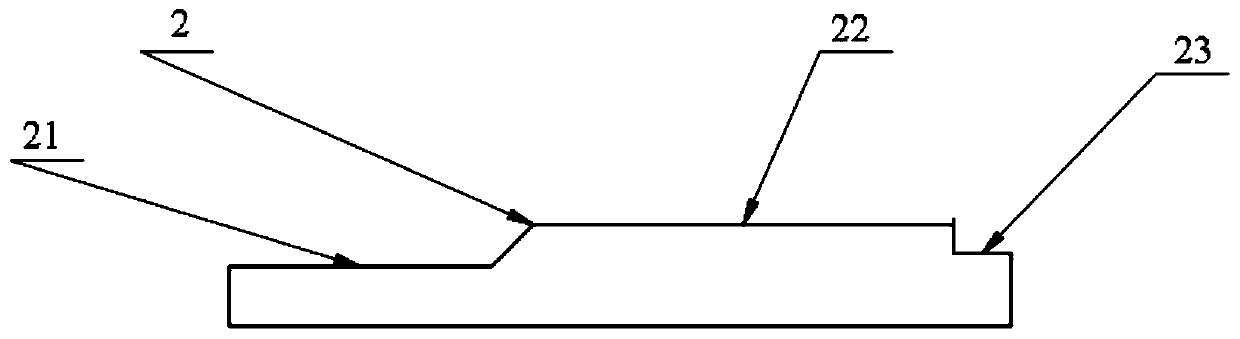
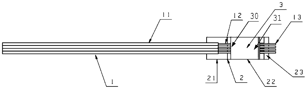
[0042] Such as figure 1 , figure 2 As shown, a substrate with a bare optical fiber array having an inclined end face includes a platform structure 21, a groove structure 22 and a pressure dispersion structure 23, and the groove structure 22 is located between the platform structure 21 and the pressure dispersion structure 23, and The upper surface of the grooved structure 22 is higher than the upper surfaces of the pressure dispersion structure 23 and the platform structure 21 , and the surface of the grooved structure 22 has grooves.

[0043] The grooves of the groove structure 22 are V-shaped grooves or U-shaped grooves.

[0044] The height difference between the grooved structure 12 and the pressure distribution structure 13 is greater than 0.15 mm, and the height difference of 0.2 mm is a better choice.

[0045] The height dif...


PUM


Abstract

The invention provides a manufacturing method and a substrate of a bare type fiber array with an inclined end face; the substrate comprises a platform structure, a notch structure and a pressure disperse structure; the fiber array manufacture method comprises the following steps: 1, clearly peeling off a wrapping layer on one end of a fiber, using alcohol to clean residuals on the surface of the bare fiber, thus forming a bare fiber portion; 2, placing the bare fiber into a notch of the notch structure, and allowing the end face of the bare fiber to extend outside the pressure disperse structure. 3, using a cover plate to cover the bare fiber zone above the notch structure; 4, dripping UV solidification glue into the boundary between the notch structure and the platform structure, and using an UV lamp to solidify the UV glue; 5, carrying out angle grinding process on the end face of the solidified fiber array, thus forming an optical slope with a specific angle. The method can solve the problems that the front bare fiber is easily broken or damaged in a bare type fiber array manufacture process, thus obviously improving fiber bare type fiber array manufacture yield, reducing material waste, and reducing making cost.

Description

technical field [0001] The invention belongs to the technical field of optical communication, and relates to a manufacturing method of an exposed optical fiber array with an inclined end face and a substrate thereof, in particular to an optical fiber array that can overcome the breakage and collapse of the exposed optical fiber during the grinding and polishing process, and significantly improve the manufacturing process. Yield rate, reduction of material loss, reduction of manufacturing cost, and method for manufacturing bare optical fiber arrays with inclined end faces. Background technique [0002] With the continuous development of human society, the requirements for communication technology are getting higher and higher, especially for large-capacity and high-speed optical communication devices. [0003] Optical fiber array is the core component widely used in planar optical waveguide devices, parallel optical transceiver modules, active optical cables and other product...

Claims


Application Information

Patent Timeline
Patent Type & Authority Patents(China)
IPC IPC(8): G02B6/36
CPCG02B6/3608
Inventor 李鹏青程琳
Owner 武汉生一升光电科技有限公司
Why Eureka
Try Eureka