Light projection angle adjusting structure of lamp
An angle adjustment and lamp technology, applied in lighting devices, lighting device parts, lighting auxiliary devices, etc., can solve the problems of short service life, the adjustment of the projection angle cannot be maintained for a long time, and achieve a wide range of applications and flexible adjustment methods. The effect of convenience and wide range of angle adjustment
- Summary
- Abstract
- Description
- Claims
- Application Information
AI Technical Summary
Problems solved by technology
Method used
Image
Examples
Embodiment Construction
[0022] In order to facilitate the understanding of those skilled in the art, the present invention will be further described in detail below in conjunction with the accompanying drawings and embodiments.
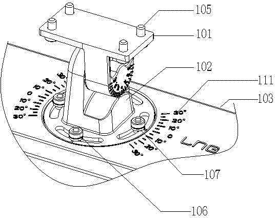
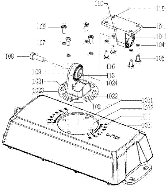
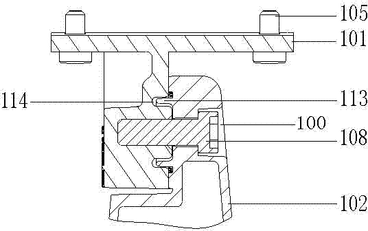
[0023] See figure 1 , the light projection angle adjustment structure of the lamp disclosed in the present invention is mainly a rotating bracket assembly, which is used to connect the lamp body and the electrical box 103 . The rotating bracket assembly includes a rotating shaft 101 and a rotating base 102. The rotating shaft 101 is fixedly connected to the lamp body, and the rotating base 102 is connected to the electrical box 103. The rotating shaft 101 drives the lamp body to rotate 180 degrees relative to the rotating base 102, so that the lamp body can be rotated by 180 degrees. Angle adjustment in the longitudinal circumferential plane; the rotating seat 102 can rotate 60 degrees relative to the electrical box 103, which drives the rotating shaft and then drives the l...
PUM
 Abstract
Description
Claims
Application Information
 - R&D
- Intellectual Property
- Life Sciences
- Materials
- Tech Scout
- Unparalleled Data Quality
- Higher Quality Content
- 60% Fewer Hallucinations
Browse by: Latest US Patents, China's latest patents, Technical Efficacy Thesaurus, Application Domain, Technology Topic, Popular Technical Reports.
© 2025 PatSnap. All rights reserved.Legal|Privacy policy|Modern Slavery Act Transparency Statement|Sitemap|About US| Contact US: help@patsnap.com


