
Angle adjusting structure for movable curtain wall

An angle-adjusting structure and curtain wall technology, applied in the direction of walls, building components, building structures, etc., can solve the problems of large material consumption, small adjustable range of angles between curtain walls, secondary blocking, etc.

Pending Publication Date: 2020-02-14
北京希绎希工程技术咨询有限公司
View PDF0 Cites 3 Cited by
  • Summary
  • Abstract
  • Description
  • Claims
  • Application Information

AI Technical Summary

Problems solved by technology

However, in the existing method, one curtain wall is installed on one column, and the splicing between the two curtain walls needs to be realized through the alignment between the two columns. Since the alignment between the columns is limited by the structure, the adjustable range of the angle between the curtain walls is small. , the use of multiple columns leads to large material consumption; at the same time, this method is also easy to cause the secondary blockage of the indoor angle between the two columns

Method used


Image

  • Angle adjusting structure for movable curtain wall
  • Angle adjusting structure for movable curtain wall
  • Angle adjusting structure for movable curtain wall

Examples


Embodiment Construction

[0050] In order to have a clearer understanding of the technical features, purposes and effects of the invention, the specific embodiments of the present invention are now described with reference to the accompanying drawings, in which the same reference numerals represent components with the same or similar structures but the same functions.

[0051] In this article, "schematic" means "serving as an example, example or illustration", and any illustration or implementation described as "schematic" should not be interpreted as a more preferred or more advantageous Technical solutions. In order to keep the drawings concise, the drawings only schematically show the parts related to this exemplary embodiment, and they do not represent the actual structure and true proportion of the product.

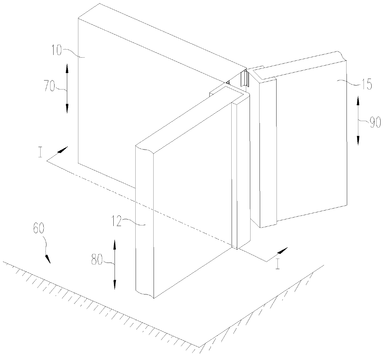
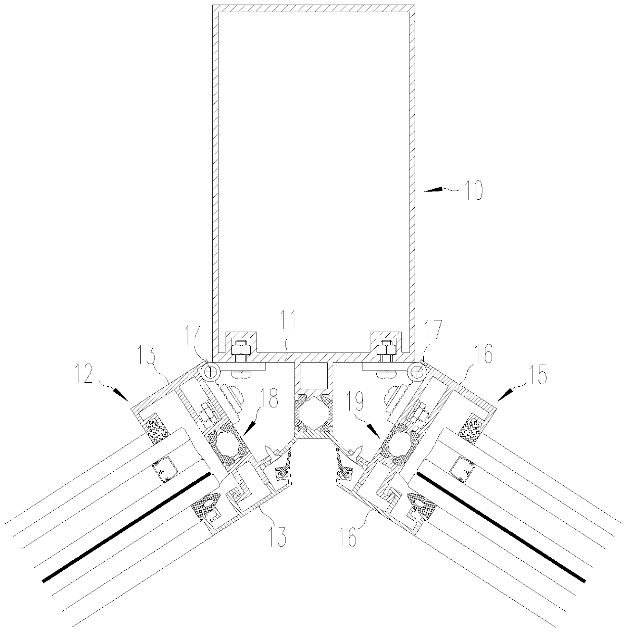
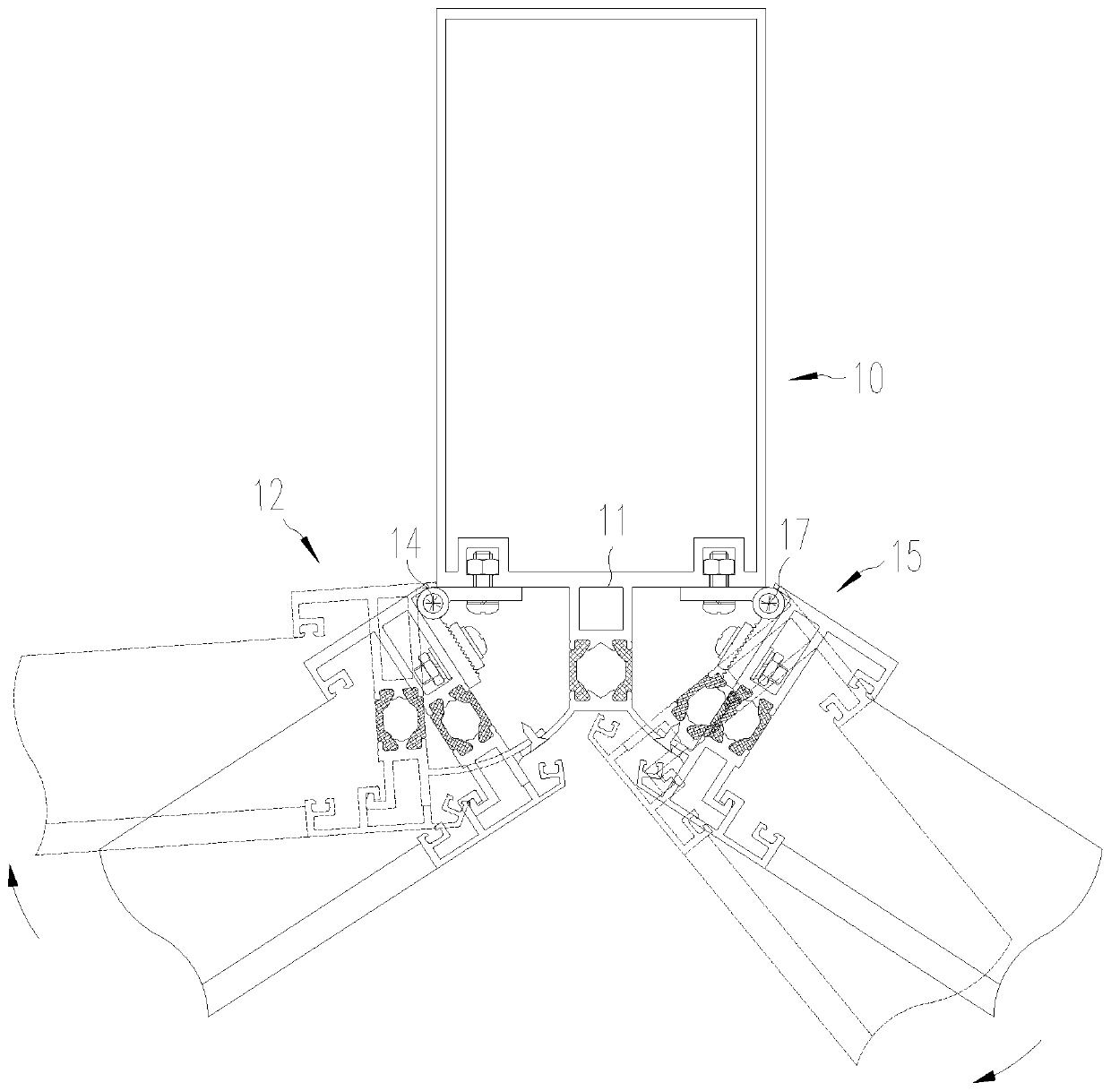
[0052] figure 1 It is a schematic diagram for explaining the angle adjustment structure of the movable curtain wall. refer to figure 1 , the present invention provides an angle adjustment ...


PUM


Abstract

The invention provides an angle adjusting structure for a movable curtain wall. The angle adjusting structure is provided with a main vertical column (10) arranged on a supporting face, a first auxiliary vertical column (12), and a second auxiliary vertical column (15); the main vertical column (10) is provided with a vertical column face (11) which is perpendicular to the supporting face; the first auxiliary vertical column is provided with a first auxiliary vertical column face (13); the first auxiliary vertical column is rotationally connected with a vertical column face of the main vertical column around a first rotary shaft (14), and the axial direction of the first rotary shaft is parallel to the extending direction of the first auxiliary vertical column; the second auxiliary vertical column is provided with a second auxiliary vertical column face (16); the second auxiliary vertical column is rotationally connected with the vertical column face of the main vertical column arounda second rotary shaft (17), and the axial direction of the second rotary shaft is parallel to the extending direction of the second auxiliary vertical column; and the second rotary shaft is parallel to the first rotary shaft, and the second rotary shaft and the first rotary shaft are spaced by a set interval. The adverse influence of curtain wall vertical column splicing on the indoor overall exterior trimming effect can be improved, material consumption can be reduced, and the angle adjustable range of the movable curtain wall is increased.

Description

technical field [0001] The invention relates to the field of building curtain walls. Specifically relates to an angle adjustment structure of a movable curtain wall. Background technique [0002] Existing public building curtain walls mostly adopt the form of broken line. Since different designs have different requirements for the change of the angle of the broken line, two profiles are often spliced ​​to meet the changing requirements of the angle. However, in the existing method, one curtain wall is installed on one column, and the splicing between the two curtain walls needs to be realized through the alignment between the two columns. Since the alignment between the columns is limited by the structure, the adjustable range of the angle between the curtain walls is small. , the use of multiple columns leads to large material consumption; at the same time, this method is also easy to cause the secondary blockage of the indoor angle between the two columns. Contents of t...

Claims


Application Information

Patent Timeline
IPC IPC(8): E04B2/88E04B2/96
CPCE04B2/88E04B2/96
Inventor 吴小卫方征罗涛颜庭强
Owner 北京希绎希工程技术咨询有限公司
Learn More