Refrigeration equipment and positioning structure for assembling reinforcer on inner container of refrigeration equipment

A positioning structure and reinforcement technology, which is applied to household refrigeration devices, lighting and heating equipment, household appliances, etc., can solve problems such as damage to other components, affect assembly and foaming, and inaccurate positioning of positioning structures, so as to achieve accurate positioning Effect

Inactive Publication Date: 2012-03-14
博西华家用电器有限公司
View PDF6 Cites 17 Cited by
  • Summary
  • Abstract
  • Description
  • Claims
  • Application Information

AI Technical Summary

Problems solved by technology

[0006] The purpose of the present invention is to provide a positioning structure for assembling reinforcements on the inner tank of refrigeration equipment and a refrigeration equipment with the positioning structure, so as to solve the problem of inaccurate positioning of the positioning structure or damage to other components in the prior art that affect assembly and foaming The problem

Method used


Image

  • Refrigeration equipment and positioning structure for assembling reinforcer on inner container of refrigeration equipment
  • Refrigeration equipment and positioning structure for assembling reinforcer on inner container of refrigeration equipment
  • Refrigeration equipment and positioning structure for assembling reinforcer on inner container of refrigeration equipment

Examples


no. 1 example

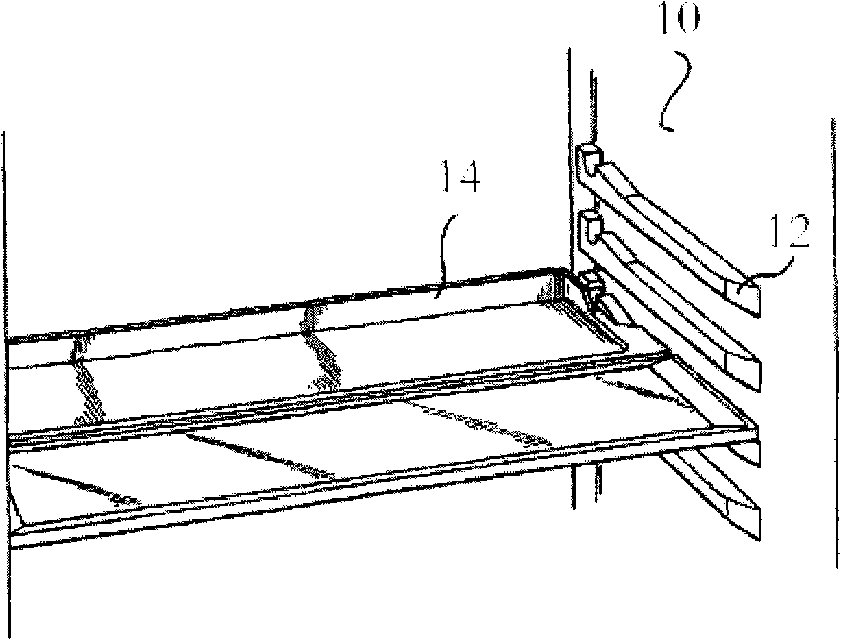
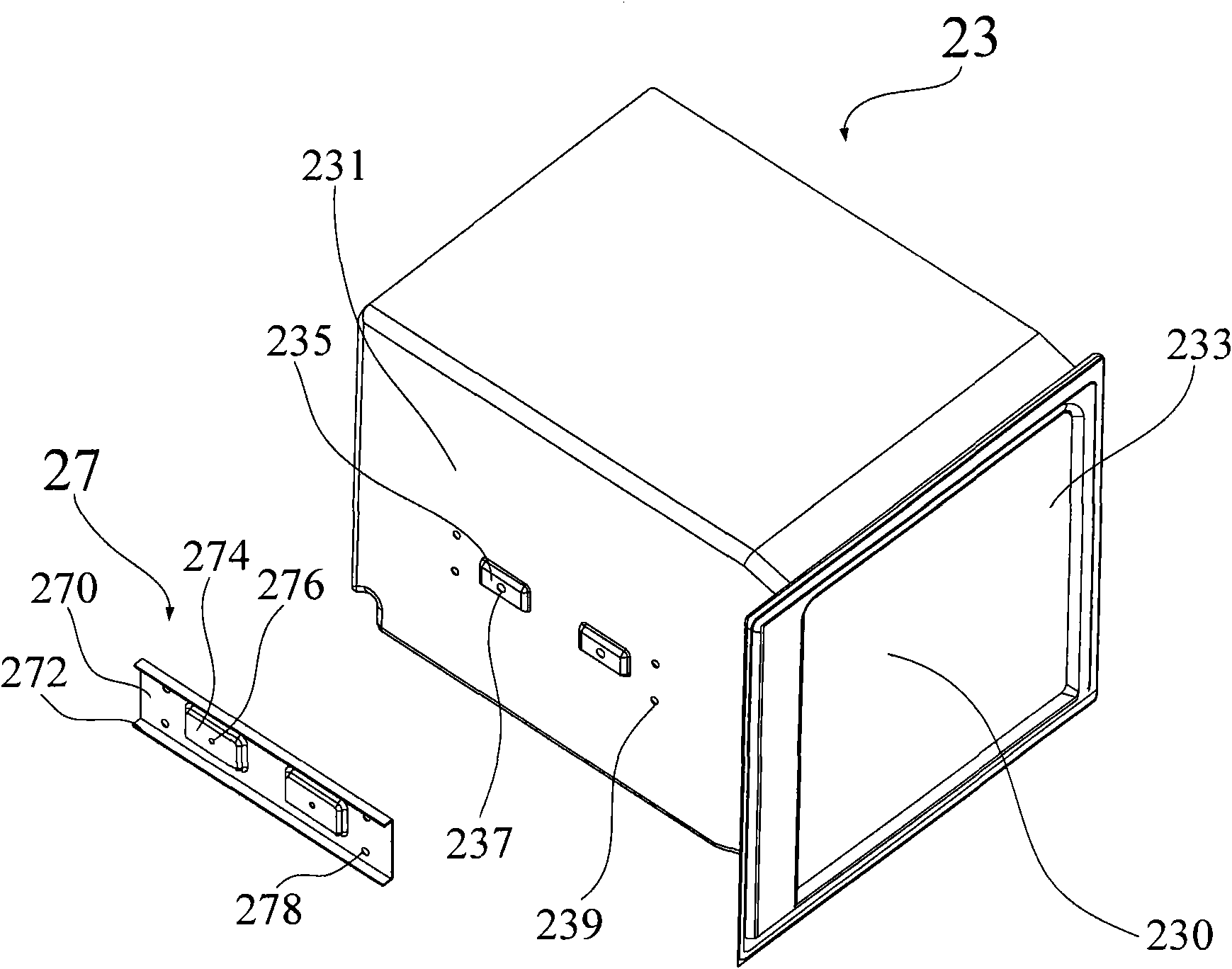
[0042] In order to accurately position the reinforcement 27 on the inner tank 23, the present invention particularly provides a positioning structure for assembling the reinforcement on the inner tank. Described positioning structure specifically comprises: be arranged on the side wall (left side wall 231 and the right side wall 233) of liner 23, the first limit boss 235 that is away from the inner wall surface of liner 23, be located at the first limit boss 235. The positioning hole 237 of the platform 235 is located on the main body portion 270 of the reinforcing member 27, away from the assembly surface of the reinforcing member 27, and the second limiting boss 274 that cooperates with the first limiting boss 235 of the liner 23 is located on the second limiting boss 274. Two limiting bosses 274, a boss 276 facing the assembly surface of the reinforcing member 27 and cooperating with the positioning hole 237 of the liner 23 (wherein for the second limiting boss 274 and the b...

no. 2 example

[0053] Please refer to Figure 8, Figure 8 It shows a partial cross-sectional schematic view of the second embodiment of the positioning structure for assembling the reinforcing member on the inner tank. Such as Figure 8 As shown, specifically, the first limiting boss 235 is formed by extending from the inner container 23, and is away from the inner wall surface of the side wall of the inner container 23; The boss 239 on the inner wall of 23 ; the second limiting boss 274 is formed by extending from the main body 270 and away from the assembly surface of the reinforcing member 27 ; the second limiting boss 274 is additionally provided with a positioning hole 278 . In this embodiment, after the first limiting boss 235 is matched with the second limiting boss 274, the protrusion 239 on the first limiting boss 235 is correspondingly inserted into the positioning hole 278 of the second positioning boss 274 When positioning, since the boss 239 is the inner wall surface away from...


PUM


Abstract

The invention relates to refrigeration equipment and a positioning structure for assembling a reinforcer on an inner container of the refrigeration equipment. The positioning structure comprises a first positioning piece and a second positioning piece, wherein the first positioning piece is arranged on the side wall of the inner container and comprises a first limiting boss away from the side wall of the inner container, and a positioning hole which is formed on the first limiting boss; and the second positioning piece is arranged on the reinforcer and comprises an assembly surface away from the reinforcer, a second limiting boss which is matched with the first limiting boss of the first positioning piece, and a protruding column which is arranged on the second limiting boss, faces the assembly surface of the reinforcer and is matched with the positioning hole of the first positioning piece. Compared with the prior art, the positioning structure has the advantages of accurate positioning, firm reinforcer assembly, and no damage to foaming moulds.

Description

technical field [0001] The invention relates to a refrigeration technology, in particular to a refrigeration equipment and a positioning structure for assembling a reinforcement on its inner tank. Background technique [0002] In order to reduce the heat exchange between inside and outside of the refrigerator, the cabinet of the refrigerator is usually provided with heat insulation performance. A traditional box includes an outer shell and an inner tank kept at a certain distance from the outer shell. A foaming operation is also required between the outer shell and the inner container to inject a thermal insulation foam agent into the gap between the two to form a thermal insulation layer, so as to isolate or reduce the heat exchange between the inside and outside of the refrigerator. [0003] Generally, the liner is made of plastic, such as ABS, with relatively small thickness and strength. Therefore, when assembling heavy-duty parts on the inner tank (such as telescopic ...

Claims


Application Information

Patent Timeline
Patent Type & Authority Applications(China)
IPC IPC(8): F25D23/10
Inventor 卢志山马敬东陶锋赵德飞杨振宇
Owner 博西华家用电器有限公司
Why Eureka
Try Eureka