Refrigerator and overturning beam thereof

A technology for turning beams and refrigerators, applied in the field of refrigerators and turning beams, can solve problems such as affecting assembly efficiency and assembly appearance, unorganized wiring harnesses, and deformation of turning beams, etc., to achieve energy saving and food preservation, improve assembly efficiency, enhance the effect of strength

Inactive Publication Date: 2012-03-14
HEFEI MIDEA REFRIGERATOR CO LTD +1
4 Cites 24 Cited by

AI-Extracted Technical Summary

Problems solved by technology

[0003] The existing problems are: during the assembly process of the sheet metal parts of the flip beam and the main body of the flip beam, because there are foam and heating wire harnesses in the middle, the assembly is inconvenient, and the wire harnesses cannot be arranged during the assembly process, which is ea...

Method used

[0041] According to an example of the present invention, the first end of the beam cover 500 is formed with a rib 520, the rib 520 is formed with a mounting hole 521, and the first end of the beam box 100 is formed with a The installation protrusion 131 passes through the installation hole 521 so that the beam cover 500 is connected with the beam body box 100 . Thus, the beam cover 500 and the beam box 100 are easily assembled, and the heating element 600 is protected.
[0042] According to some examples of the present invention, the thermal insulation member 300 is thermal insulation foam. Therefore, the structure is simple, the forming is convenient, and the production cost is reduced.
[0043] According to a specific example of the present invention, the first hinge seat 220a is a pivot hole 221a, and the second hinge seat 220b is a pivot hole (not shown). The first hinge 410 is formed with a pivot 411 adapted to the pivot hole 221a of the first hinge seat 220a, and the second hinge 420 is formed with a pivot 421 adapted to the pivot hole of the second hinge seat 220b. The pivot 411 of 410 is inserted into the pivot hole 221a of the first hinge base 220a, and the pivot 421 of the second hing...

Abstract

The invention discloses an overturning beam for a refrigerator and the refrigerator with the overturning beam. The overturning beam for the refrigerator comprises a beam body box, a beam body, an insulation member, a first hinge and a second hinge, a beam cover and a heating part, wherein a first cavity is limited in the beam body box, a second cavity is limited on the upper surface of the beam body and a third cavity is formed on the lower surface of the beam body, the beam body is arranged in the first cavity to ensure that the first cavity and the third cavity form a first accommodating cavity; the insulation member is arranged in the first accommodating cavity; and the heating part is arranged in a second accommodating cavity. According to the overturning beam for the refrigerator, provided by the embodiment of the invention, the sealing of the refrigerator is improved, and the energy saving and the food refreshing are facilitated. The assembly mode of the overturning beam is simplified, and the assembling efficiency is increased. The strength of the overturning beam is enhanced so that the overturning beam is not easy to deform, and the service life of the overturning beam is prolonged.

Application Domain

Technology Topic

Image

  • Refrigerator and overturning beam thereof
  • Refrigerator and overturning beam thereof
  • Refrigerator and overturning beam thereof

Examples

  • Experimental program(1)

Example Embodiment

[0027] The embodiments of the present invention will be described in detail below. Examples of the embodiments are shown in the accompanying drawings, wherein the same or similar reference numerals indicate the same or similar elements or elements with the same or similar functions. The embodiments described below with reference to the drawings are exemplary, and are only used to explain the present invention, but should not be understood as limiting the present invention.
[0028] In the description of the present invention, it should be understood that the terms "center", "longitudinal", "transverse", "upper", "lower", "front", "rear", "left", "right", " The orientation or positional relationship indicated by "vertical", "horizontal", "top", "bottom", "inner", "outer", etc. are based on the orientation or positional relationship shown in the drawings, and are only for the convenience of describing the present invention and simplifying The description does not indicate or imply that the pointed device or element must have a specific orientation, be constructed and operated in a specific orientation, and therefore cannot be understood as a limitation of the present invention.
[0029] In addition, the terms "first" and "second" are only used for descriptive purposes, and cannot be understood as indicating or implying relative importance.
[0030] In the description of the present invention, it should be noted that the terms "installed", "connected", and "connected" should be understood in a broad sense unless otherwise clearly specified and limited. For example, they may be fixedly connected, integrally connected, or It can be a detachable connection; it can be a mechanical connection or an electrical connection, or it can be the internal communication between the two components; it can be directly connected or indirectly connected through an intermediate medium. For those of ordinary skill in the art, it can be based on specific Understand the specific meaning of the above terms.
[0031] The turning beam for a refrigerator according to an embodiment of the present invention will be described in detail below with reference to the accompanying drawings.
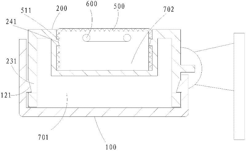
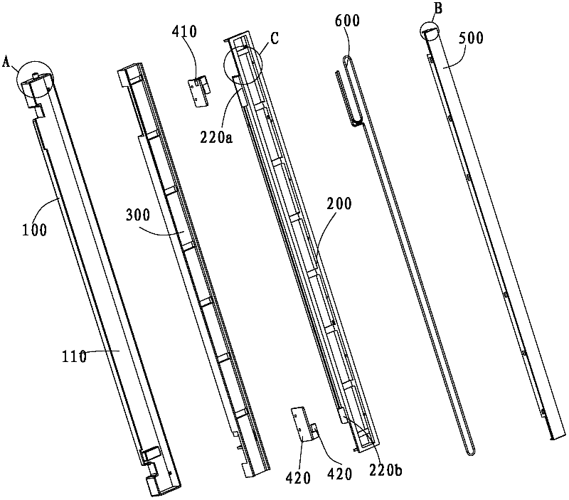
[0032] Such as Figure 1-6 As shown, the turning beam for a refrigerator according to an embodiment of the present invention includes: a beam box 100, a beam body 200, an insulating member 300, a first hinge 410, a second hinge 420, a beam cover 500 and a heating component 600,
[0033] Specifically, the beam box 100 defines a first cavity 110 and the top surface of the first cavity 110 is open.
[0034] A second cavity 210a is defined on the upper surface of the beam body 200, and a third cavity 210b is formed on the lower surface of the beam body 200. The beam 200 is disposed in the first cavity 110, and the first cavity 110 and the third cavity 210 b cooperate to form a first receiving cavity 701. The first end of the beam 200 is formed with a first hinge seat 220a, and the second end of the beam 200 is formed with a second hinge seat 220b.
[0035] The heat insulating member 300 is arranged in the first containing cavity 701.
[0036] The first hinge 410 is connected to the first hinge base 220 a of the beam body 200, and the second hinge 420 is connected to the second hinge base 220 b of the beam body 200.
[0037] The beam cover 500 is connected to the beam body 200, and the beam cover 500 and the second cavity 210 a form a second receiving cavity 702. The beam cover 500 is connected to the beam box 100.
[0038] The heating component 600 is provided in the second receiving cavity 702.
[0039] According to the flip beam used in the refrigerator according to the embodiment of the present invention, the first cavity 110 on the beam box 100 and the second cavity 210a on the beam body 200 cooperate to form the first receiving cavity 701, and the third cavity on the beam body 200 The cavity 210b cooperates with the beam cover 500 to form a second receiving cavity 702. Wherein, the heat preservation member 300 is arranged in the first accommodating cavity 701, and the heating component 600 is arranged in the second accommodating cavity 702. As a result, the assembly method of the turning beam according to the embodiment of the present invention is simplified, the assembly efficiency is improved, and the strength of the turning beam is enhanced at the same time, so that the turning beam is not easily deformed, and the service life is improved.
[0040] According to an embodiment of the present invention, a first hook 121 is formed on the beam box 100, a first groove 231 is formed on the beam 200, and the first groove 231 is matched with the first hook 121, and the beam The box 100 is clamped to the beam body 200. Advantageously, according to some embodiments of the present invention, a second hook 241 is formed on the beam body 200, and a second hook 511 is formed on the beam cover 500, and the second hook 511 is matched with the second hook 121. The beam body 200 is clamped to the beam cover 500. Thus, the beam box 100 and the beam body 200 are tightly combined, and the beam body 200 and the beam cover 500 are tightly combined, so that the sealing performance of the turning beam according to the embodiment of the present invention is improved. At the same time, the assembly and disassembly are convenient, and the assembly efficiency is improved.
[0041] According to an example of the present invention, the first end of the beam cover 500 is formed with a protruding rib 520, a mounting hole 521 is formed on the protruding rib 520, and a first end of the beam box 100 is formed with a mounting protrusion that matches the mounting hole 521. From 131, the mounting protrusion 131 passes through the mounting hole 521 to connect the beam cover 500 with the beam box 100. As a result, the beam cover 500 and the beam body box 100 are easy to assemble, and the heating element 600 is protected.
[0042] According to some examples of the present invention, the thermal insulation member 300 is thermal insulation foam. Therefore, the structure is simple, the molding is convenient, and the production cost is reduced.
[0043] According to a specific example of the present invention, the first hinge seat 220a is a pivot hole 221a, and the second hinge seat 220b is a pivot hole (not shown). The first hinge 410 is formed with a pivot 411 that is adapted to the pivot hole 221a of the first hinge base 220a, and the second hinge 420 is formed with a pivot 421 that is adapted to the pivot hole of the second hinge base 220b. The first hinge The pivot 411 of the 410 is inserted into the pivot hole 221a of the first hinge base 220a, and the pivot 421 of the second hinge 420 is inserted into the pivot hole of the second hinge base 220b. As a result, the first hinge 220a and the second hinge 220b can be easily assembled with the beam body 200, and the turning beam according to the embodiment of the present invention can be pivotally connected to the refrigerator door body.
[0044] According to some embodiments of the present invention, the beam cover 500 is a sheet metal part. Therefore, it is easy to form, convenient to produce, and save cost. At the same time, the beam cover 500 is beautiful and strong.
[0045] According to a specific embodiment of the present invention, the heating component 600 is a heating wire. As a result, the turning beam according to the embodiment of the present invention can be easily heated, which is beneficial to the defrosting of the turning beam, and the operation is convenient.
[0046] The refrigerator according to the embodiment of the present invention includes: a box body (not shown), a first door body (not shown), a second door body (not shown) and a turning beam.
[0047] Specifically, a compartment (not shown) is defined in the box.
[0048] The first door body is installed on the box body, the second door body is installed on the box body, and the first door body and the second door body are used to open and close the compartment . Wherein, the first door body is located on the left side of the second door body.
[0049] The turning beam is installed on the first door body or the second door body, and the turning beam is rotatable on the first door body or the second door body. The turning beam rotates backward when the first door body or the second door body is opened, the turning beam rotates forward when the first door body or the second door body is closed, and the turning beam forwards The rotation can close the gap between the first door body and the second door body, wherein the turning beam is a turning beam for a refrigerator according to the foregoing embodiment of the present invention.
[0050] According to the refrigerator of the embodiment of the present invention, the first door body or the second door body is installed with the turning beam for the refrigerator according to the foregoing embodiment of the present invention. Therefore, the sealing effect of the refrigerator is improved, which is beneficial to energy saving and food preservation. The assembly method of the turning beam is simplified, and the assembly efficiency is improved. At the same time, the strength of the turning beam is enhanced, the turning beam is not easily deformed, and the service life of the turning connection is improved.
[0051] In the description of this specification, descriptions with reference to the terms "one embodiment", "some embodiments", "examples", "specific examples", or "some examples" etc. mean specific features described in conjunction with the embodiment or example , Structure, materials or features are included in at least one embodiment or example of the present invention. In this specification, the schematic representations of the above terms do not necessarily refer to the same embodiment or example. Moreover, the described specific features, structures, materials or characteristics may be combined in any one or more embodiments or examples in a suitable manner.
[0052] Although the embodiments of the present invention have been shown and described, those of ordinary skill in the art can understand that various changes, modifications, substitutions, and modifications can be made to these embodiments without departing from the principle and purpose of the present invention. The scope of the present invention is defined by the claims and their equivalents.

PUM

no PUM

Description & Claims & Application Information

We can also present the details of the Description, Claims and Application information to help users get a comprehensive understanding of the technical details of the patent, such as background art, summary of invention, brief description of drawings, description of embodiments, and other original content. On the other hand, users can also determine the specific scope of protection of the technology through the list of claims; as well as understand the changes in the life cycle of the technology with the presentation of the patent timeline. Login to view more.

Similar technology patents

Handling manipulator

Owner:江苏有能电气成套有限公司

Classification and recommendation of technical efficacy words

  • Improve assembly efficiency
  • Easy assembly

Automatic assembling device and assembling method for valve rod sealing rings

InactiveCN103465005ASmall support ringImprove assembly efficiencyMetal working apparatusEngineeringAssembly automation
Owner:TAIZHOU LIANFANG ELECTROMECHANICAL TECH

Photosensitive drum driving assembly

Owner:PRINT RITE UNICORN IMAGE PROD CO LTD OF ZHUHAI

Gas sensor

Owner:RAE SYST SHANGHAI
Why Eureka
Try Eureka