Touch control display panel and manufacture method thereof

A technology of touch display panel and touch panel, which is applied in the direction of instrument, electrical digital data processing, input/output process of data processing, etc.

Inactive Publication Date: 2012-03-14
DONGGUAN MASSTOP LIQUID CRYSTAL DISPLAY +1
View PDF4 Cites 11 Cited by
  • Summary
  • Abstract
  • Description
  • Claims
  • Application Information

AI Technical Summary

Problems solved by technology

The display panel is electricall

Method used


Image

  • Touch control display panel and manufacture method thereof
  • Touch control display panel and manufacture method thereof
  • Touch control display panel and manufacture method thereof

Examples


no. 1 example

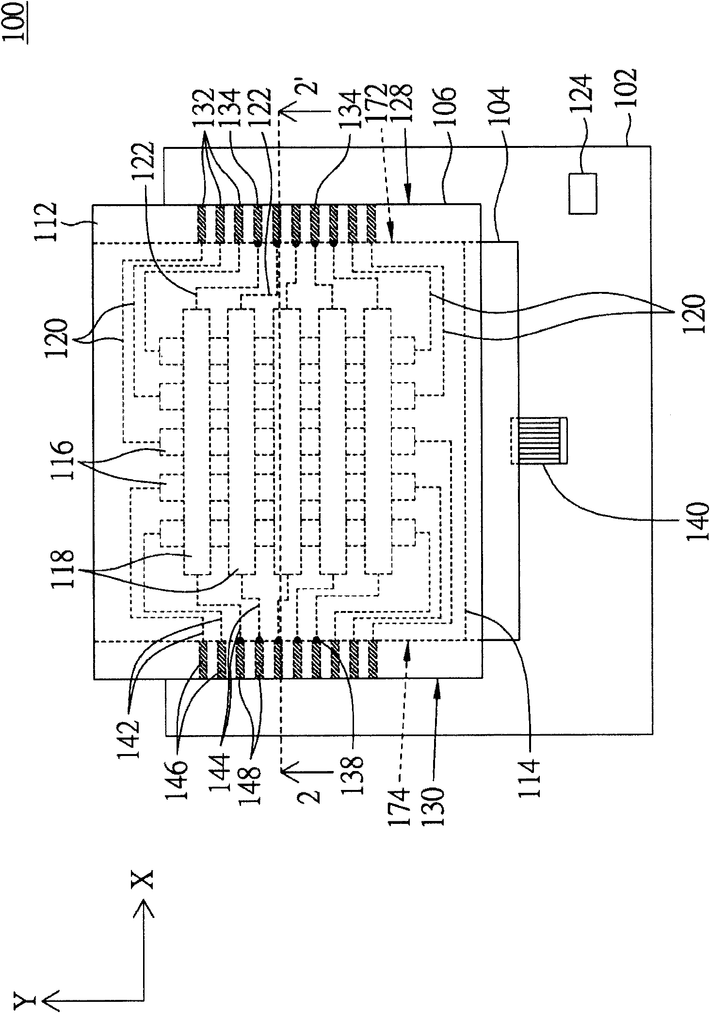
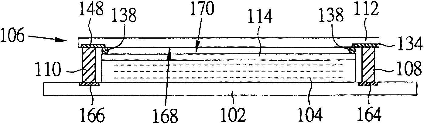
[0051] Please refer to figure 1 and figure 2 , figure 1 It shows the top view of the touch display panel according to the first embodiment of the present invention, figure 2 draw figure 1 Sectional view of 2-2' in the middle direction.

[0052] like figure 1 As shown, the touch display panel 100 includes a circuit board 102, a display panel 104, a touch panel 106, a first conductive glue 108 and a second conductive glue 110 (the first conductive glue 108 and the second conductive glue 110 are shown in figure 2 ). Wherein, the touch panel 106 is a resistive touch panel.

[0053] The touch panel 106 includes a plurality of signal lines and a first substrate 112 and a second substrate 114 disposed opposite to each other. The signal lines include several first signal lines 120 , several second signal lines 122 , several third signal lines 142 and several fourth signal lines 144 .

[0054] The first substrate 112 includes a plurality of first sensing lines 116 , a plural...

no. 2 example

[0080] Please refer to Figure 4 , which is a schematic diagram of a display touch panel according to a second embodiment of the present invention. The parts in the second embodiment that are the same as those in the first embodiment use the same reference numerals, which will not be repeated here. The display touch panel 200 of the second embodiment is different from the display touch panel 100 of the first embodiment in that the signal pads of the display touch panel 200 are disposed corresponding to four sides of the first substrate.

[0081] The touch panel 206 of the display touch panel 200 is, for example, a resistive touch panel, which includes a plurality of signal lines 262 and a first substrate 212 and a second substrate 214 disposed opposite to each other.

[0082] The first substrate 212 includes a plurality of first sensing lines 116 , a plurality of first signal pads 254 , a plurality of second signal pads 256 , a plurality of third signal pads 258 and a plurali...

no. 3 example

[0088] Please refer to Figure 5 and Image 6 , Figure 5 It shows the top view of the touch display panel according to the third embodiment of the present invention, Image 6 draw Figure 5 Sectional view of 6-6' in the middle direction. The parts in the third embodiment that are the same as those in the first embodiment use the same reference numerals, which will not be repeated here. The touch display panel 300 of the third embodiment is different from the touch display panel 100 of the first embodiment in that the sensing lines of the touch panel 306 of the touch display panel 300 are formed on a single substrate.

[0089] The touch panel 306 is, for example, a capacitive touch panel, which includes a plurality of signal lines 362 and a substrate 312 . The substrate 312 includes a plurality of first sensing lines 316 and a plurality of second sensing lines 318 . The first sensing line 316 , the second sensing line 318 and the signal line 362 are all formed on the sub...


PUM


Abstract

The invention discloses a touch control display panel and a manufacture method thereof. The touch control display panel comprises a circuit board, a display panel, a touch control panel, a first conductive adhesive and a second conductive adhesive, wherein the display panel is electrically connected with the circuit board; the touch control panel is electrically connected with the circuit board and comprises a base plate and a plurality of signal lines; the base plate comprises a plurality of first signal joint pads and a plurality of second signal joint pads; the first signal joint pads correspond to the first side edge of the base plate, and the second signal joint pads correspond to the second side edge of the base plate; the signal lines are arranged at the base plate and used for transmitting touch control signals; each signal line is electrically connected with one of the first signal joint pads or one of the second signal joint pads; and the first conductive adhesive is electrically connected with the first signal joint pad and the circuit board; and the second conductive adhesive is electrically connected with the second signal joint pad and the circuit board.

Description

technical field [0001] The present invention relates to a touch display panel and a manufacturing method thereof, and in particular to a touch display panel with signal pads arranged on multiple sides of a substrate and a manufacturing method thereof. Background technique [0002] With the development of technology, the application of touch panels is becoming more and more common. The touch panel generally includes several sensing lines, several signal lines and several signal pads. The signal line is electrically connected to the corresponding sensing line and the signal pad. [0003] Generally speaking, all the signal pads are mostly arranged on the same side of the touch panel, which causes the signal lines to be squeezed into a limited space and increases the complexity of the design. Furthermore, due to the limitation of the positions of the signal pads, the lengths of some signal lines vary greatly, which affects the sensing accuracy. Contents of the invention [...

Claims


Application Information

Patent Timeline
IPC IPC(8): G06F3/041
Inventor 何昆璋赖志章廖小惠
Owner DONGGUAN MASSTOP LIQUID CRYSTAL DISPLAY
Why Eureka
Try Eureka