Wall-mounted high-current socket

A high-current, wall-mounted technology, used in circuits, electrical components, coupling devices, etc., can solve problems such as damage, copper foil aging and peeling, fire, etc., and achieve the effects of reliable operation, compact structure and strong practicability

Active Publication Date: 2013-08-07
SHANGHAI ELECTRICAL APP RES INST +1
View PDF1 Cites 0 Cited by
  • Summary
  • Abstract
  • Description
  • Claims
  • Application Information

AI Technical Summary

Problems solved by technology

[0005] No matter which method is used in the above two prior art methods, it is impossible to avoid the flow of a part of the current on the control circuit board. This is because the heat is not large for electrical equipment with a rated current of several amperes and below. Can basically meet the requirements of use
But for larger power consumption equipment (such as cabinet air conditioner 3P power up to 3KW, based on the household voltage of 220V, the current is about 14A, and the current at the start time can reach nearly 42A), due to the large current, the calorific value and The current is proportional to the square, and the heat is serious. The wiring method of the copper clad layer on the control circuit board basically cannot meet the requirements of use. If a large current is passed on the control circuit board for a long time, the copper foil will age and peel off, resulting in damage, and even cause Fire and other major safety hazards

Method used


Image

  • Wall-mounted high-current socket
  • Wall-mounted high-current socket
  • Wall-mounted high-current socket

Examples


Embodiment Construction

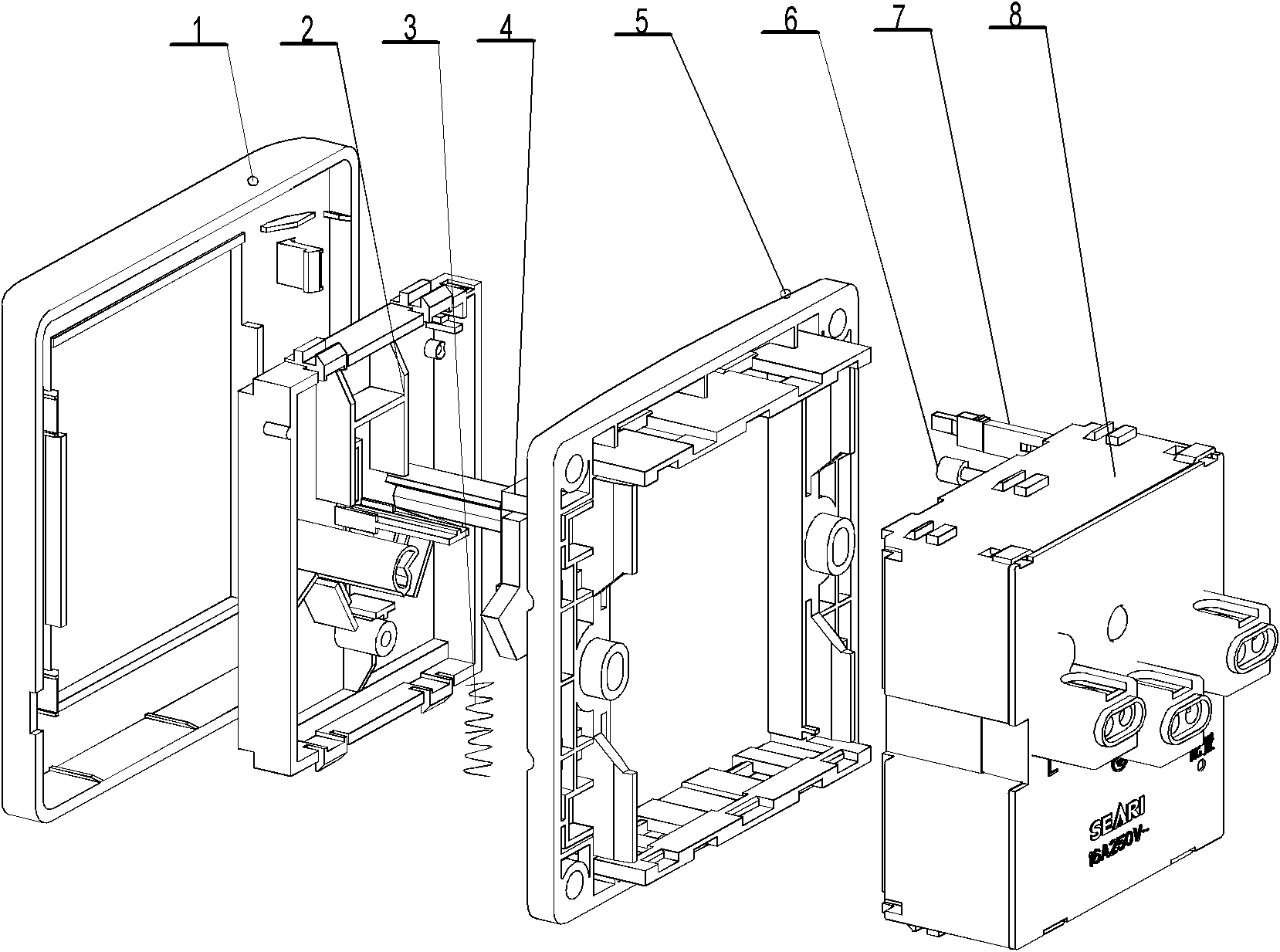
[0011] The embodiment of the present invention is further described below in conjunction with the accompanying drawings: the present invention is made up of shell cover 1, face shell 2, compression spring 3, protective door 4, light guide column 5, reset lever 6, frame 7, control submodule 8, see figure 1 . Among them, the frame 7 is a hollow structure with mounting ribs, and the face shell 2 is assembled on the front side of the frame 7 through buckles, and then the protective door 4 and the compression spring 3 are sequentially installed, see figure 1 .

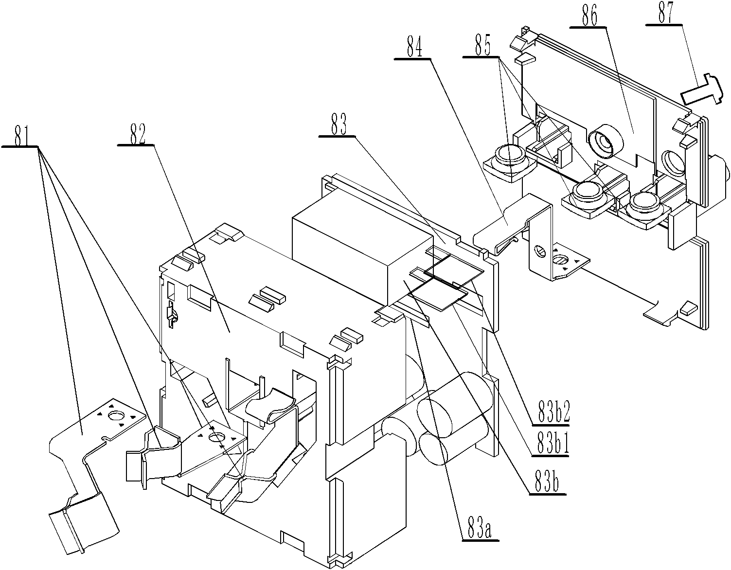
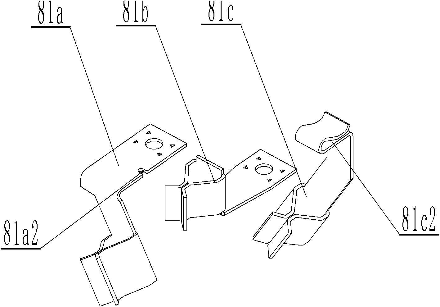
[0012] The control sub-module 8 includes a socket 81 (including three poles of L, N, and E), a housing 82, a control circuit board 83, a connecting plate 84, a crimping terminal 85, a rear cover plate 86, and fastening screws 87. Among them, the N pole socket 81a, the E pole socket 81b, and the L pole socket 81c are a separate part, and the user plug ends of the three sockets are all clamping structures, and the N pole soc...


PUM


Abstract

The invention relates to a wall-mounted high-current socket. A shell adopts a structure with the front part being isolated from the rear part, a plug sleeve is arranged in a plug sleeve inner cavity on the front face of the shell, and an N pole and an E pole plug sleeve are directly connected with an N pole wire and an E pole wire of a power supply; and an L pole plug sleeve is connected with an outgoing wire pin of a relay through a clamping structure, the incoming wire pin of the relay is connected with a clamping structure of a connecting plate, the connecting plate is directly connected with the L pole incoming wire of the power supply, the L pole plug sleeve, the relay on a control circuit board, the connecting plate and the L pole incoming wire of the power supply are connected to form a connection loop, the shell is provided with a light guide column mounting cavity and a resetting rod through hole, a resetting rod and a light guide column are arranged in the light guide columnmounting cavity and the resetting rod through hole, and the rear side of the shell is provided with the control circuit board. The invention has the advantages that the plug sleeves are effectively integrated with the control circuit board based on structural improvement of the traditional socket, the needs of intelligent control and energy conservation of power-consuming devices can be satisfied, and the wall-mounted high-current socket has a compact structure and high practicality and can work reliably.

Description

technical field [0001] The invention relates to a low-voltage electrical device, in particular to a wall-mounted high-current socket. Background technique [0002] As the power access point of household appliances, the socket is mainly a traditional mechanical structure socket. This type of socket is completely connected by copper bars, which can meet the needs of various current specifications, but the disadvantage is that the socket itself is always charged, and the electrical appliances connected to it It will always be in a standby state, which is neither safe nor able to meet the needs of energy saving, nor can it meet the needs of modern home intelligent control. [0003] With the development of electronic technology, electronic control sockets gradually enter the market. In order to meet the requirements of interchangeable installation, this type of socket has the same appearance and installation dimensions as traditional mechanical structural sockets. It can be said...

Claims


Application Information

Patent Timeline
Patent Type & Authority Patents(China)
IPC IPC(8): H01R13/10H01R13/502H01R13/66H01R13/70H01R4/28
Inventor 张业
Owner SHANGHAI ELECTRICAL APP RES INST
Why Eureka
Try Eureka