[0024] In view of the problems in the prior art, the present invention proposes a link transmission scheme, which can reduce coexistence interference and improve the utilization rate of spectrum resources, and is simple and convenient to implement, and facilitates popularization.
[0025] In order to make the technical solution of the present invention clearer and more comprehensible, the solution of the present invention will be further described in detail below with reference to the drawings and embodiments.
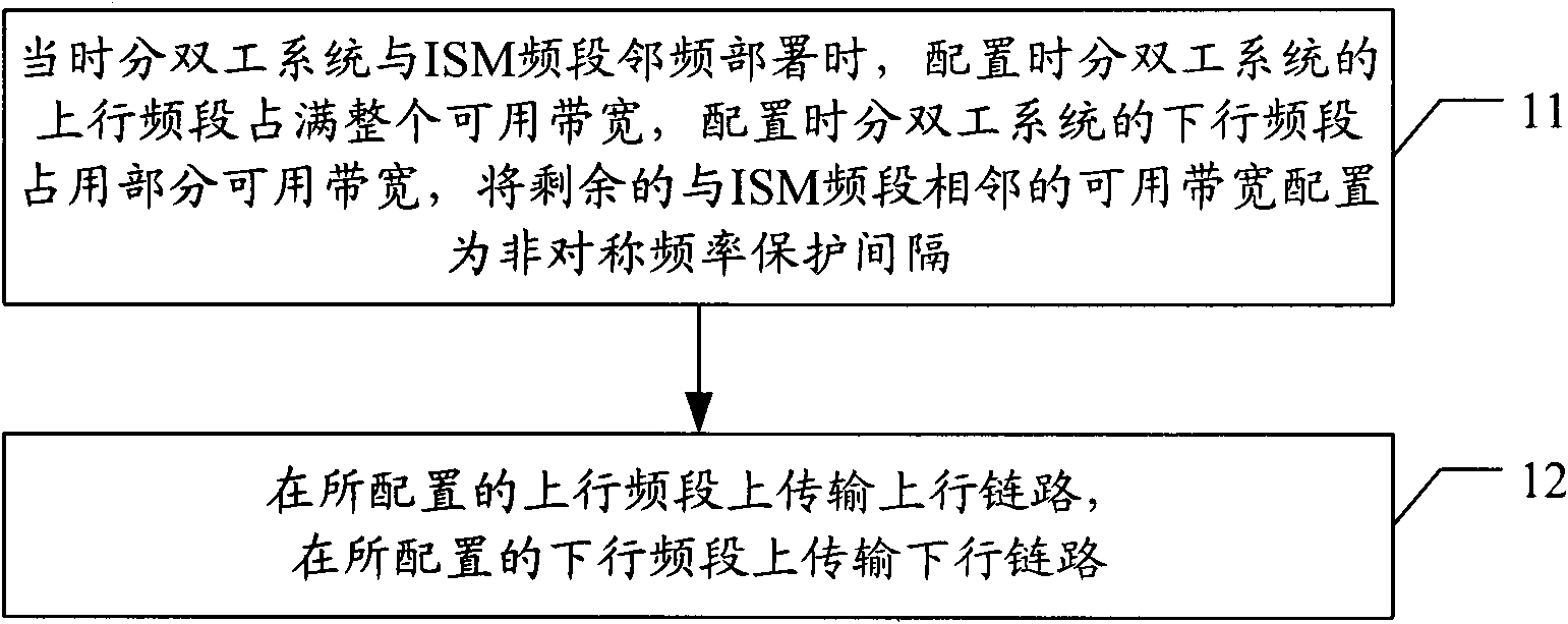
[0026] figure 1 It is a flowchart of a method embodiment of the present invention. Such as figure 1 As shown, including the following steps:
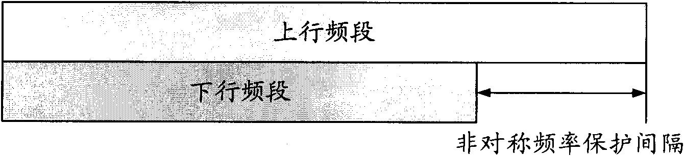
[0027] Step 11: When the time division duplex system and the ISM frequency band are deployed adjacent to the frequency, the uplink frequency band of the time division duplex system is configured to occupy the entire available bandwidth, and the downlink frequency band of the time division duplex system is configured to occupy part of the available bandwidth, and the remaining frequency is relative to the ISM frequency band. The adjacent available bandwidth is configured as an asymmetric frequency guard interval.
[0028] Those skilled in the art know that due to the characteristics of the base station itself and some other reasons, the coexistence interference in the uplink direction can usually be solved by planning deployment or hardware design. Therefore, only the coexistence interference in the downlink direction is considered in the solution of the present invention.
[0029] In this step, the uplink frequency band of the time division duplex system is configured to occupy the entire available bandwidth, that is, the 100MHz bandwidth of 2300~2400MHz, the downlink frequency band occupies part of the available bandwidth, and the remaining available bandwidth adjacent to the ISM frequency band is configured as asymmetric frequency guard interval , Through the asymmetric frequency guard interval to achieve the purpose of reducing coexistence interference. figure 2 It is a schematic diagram of the configuration of the uplink and downlink frequency bands in the method embodiment of the present invention.
[0030] In addition, in this embodiment, the downlink frequency band and the asymmetric frequency guard interval can be configured in the following three ways.
[0031] image 3 It is a flowchart of the first method of configuring the downlink frequency band and the asymmetric frequency guard interval in the method embodiment of the present invention. Such as image 3 As shown, including the following steps:
[0032] Step 31: Determine the area where the out-of-band spurious radiation power from the ISM frequency band received on the unit measurement bandwidth within the entire available bandwidth is less than or equal to the preset first threshold.
[0033] In practical applications, the required area can be determined by analyzing or testing the out-of-band spurious radiation characteristics of the ISM frequency band.
[0034] Step 32: Configure the area as a downlink frequency band.
[0035] Step 33: Configure the remaining area as an asymmetric frequency guard interval.
[0036] Figure 4 It is a flowchart of the second method of configuring the downlink frequency band and the asymmetric frequency guard interval in the method embodiment of the present invention. Such as Figure 4 As shown, including the following steps:
[0037] Step 41: Determine an area where the received interference signal power from the ISM frequency band within the entire available bandwidth is less than or equal to a preset second threshold.
[0038] In practical applications, the required area can be determined by analyzing the blocking characteristics of the terminal in the time division duplex system.
[0039] Step 42: Configure the area as a downlink frequency band.
[0040] Step 43: Configure the remaining area as an asymmetric frequency guard interval.
[0041] Figure 5 It is a flowchart of the third method of configuring the downlink frequency band and the asymmetric frequency guard interval in the method embodiment of the present invention. Such as Figure 5 As shown, including the following steps:
[0042] Step 51: Determine the area where the out-of-band spurious radiation power from the ISM frequency band received in the unit measurement bandwidth within the entire available bandwidth is less than or equal to the preset first threshold, and the interference from the ISM frequency band received within the entire available bandwidth The area where the signal power is less than or equal to the preset second threshold.
[0043] Step 52: Configure the smaller of the two areas as a downlink frequency band.
[0044] Step 53: Configure the remaining area as an asymmetric frequency guard interval.
[0045] It can be seen that this method is a synthesis of the first two methods.
[0046] The specific values of the first threshold and the second threshold may be determined according to actual needs.
[0047] In addition, the above three methods are only examples and are not used to limit the technical solutions of the present invention. In practical applications, it is also possible to use other methods to achieve the same purpose.
[0048] Step 12: Transmit the uplink on the configured uplink frequency band, and transmit the downlink on the configured downlink frequency band.
[0049] The time slot division and synchronization requirements for uplink and downlink transmission are the same as those in the prior art. In addition, the specific implementation of this step is also the same as that in the prior art, and will not be repeated.
[0050] The solution of the present invention will be further illustrated by specific examples below.
[0051] Assuming that the TD-LTE system is planned to be deployed in the 2300-2400MHz frequency band, and WLAN has been deployed in the ISM frequency band, in order to avoid coexistence and interference between the two and improve the utilization of spectrum resources, based on the idea of the present invention, TD-LTE is configured -The uplink frequency band of the LTE system occupies the entire available bandwidth, the downlink frequency band of the TD-LTE system is configured to occupy part of the available bandwidth, and the remaining available bandwidth adjacent to the WLAN is configured as an asymmetric frequency guard interval.
[0052] Assuming that the TD-LTE system can tolerate the WLAN out-of-band spurious radiation power threshold of -51dBm received per 100KHz measurement bandwidth, after testing, the UE transmitter in the deployed WLAN has a leaked band in the 2300-2400MHz frequency band. The external spurious radiation power is: taking 2370MHz as the demarcation point, the WLAN out-of-band spurious radiation power received in the previous frequency band is lower than or equal to -51dBm, and the WLAN out-of-band spurious radiation power received in the subsequent frequency band is higher than -51dBm, then configure 2300-2370MHz as the downlink frequency band of the TD-LTE system, and configure 2370-2400MHz as an asymmetric frequency guard interval, totaling 30MHz. Such as Image 6 As shown, Image 6 It is a schematic diagram of the configuration of the uplink and downlink frequency bands in the example of the present invention.
[0053] Based on the above introduction, Figure 7 It is a schematic diagram of the composition structure of the device embodiment of the present invention. Such as Figure 7 Shown, including:
[0054] The configuration unit 71 is used to configure the uplink frequency band of the time division duplex system to occupy the entire available bandwidth when the time division duplex system is deployed adjacent to the ISM frequency band, configure the downlink frequency band of the time division duplex system to occupy part of the available bandwidth, and combine the remaining The adjacent available bandwidth of the ISM frequency band is configured as an asymmetric frequency guard interval;
[0055] The transmission unit 72 is configured to transmit the uplink on the configured uplink frequency band, and transmit the downlink on the configured downlink frequency band.
[0056] Wherein, the configuration unit 71 may specifically include:
[0057] The first configuration subunit 711 is configured to configure the uplink frequency band of the time division duplex system to occupy the entire available bandwidth;
[0058] The second configuration subunit 712 is used to determine the area where the out-of-band spurious radiation power from the ISM frequency band received on the unit measurement bandwidth within the entire available bandwidth is less than or equal to the preset first threshold, and configure the area as a downlink frequency band , Configure the remaining area as asymmetric frequency guard interval;
[0059] or,
[0060] The second configuration subunit 712 is used to determine an area where the received interference signal power from the ISM frequency band within the entire available bandwidth is less than or equal to a preset second threshold, configure the area as a downlink frequency band, and configure the remaining area as a non- Symmetric frequency guard interval;
[0061] Or,
[0062] The second configuration subunit 712 is used to determine the area where the out-of-band spurious radiation power from the ISM frequency band received in the unit measurement bandwidth within the entire available bandwidth is less than or equal to the preset first threshold, and the area received within the entire available bandwidth If the interference signal power from the ISM frequency band is less than or equal to the preset second threshold, the smaller of the two areas is configured as the downlink frequency band, and the remaining area is configured as the asymmetric frequency guard interval.
[0063] Figure 7 Please refer to the specific workflow of the device embodiment shown figure 1 The corresponding description in the illustrated method embodiment will not be repeated.
[0064] In a word, adopting the technical scheme of the present invention can reduce coexistence interference and improve the utilization rate of spectrum resources, and it is simple and convenient to realize and easy to popularize.
[0065] The above are only the preferred embodiments of the present invention and are not intended to limit the present invention. Any modification, equivalent replacement, improvement, etc. made within the spirit and principle of the present invention shall be included in the present invention Within the scope of protection.