
Breath light control circuit

A technology for controlling circuits and breathing lights, which is applied in the field of non-portable lighting devices or systems, and can solve problems such as high cost, multiple devices, and advanced main chips, and achieve the effect of simple structure and cost reduction

Active Publication Date: 2012-03-14
HEFEI MIDEA REFRIGERATOR CO LTD +1
View PDF4 Cites 19 Cited by
  • Summary
  • Abstract
  • Description
  • Claims
  • Application Information

AI Technical Summary

Problems solved by technology

[0004] (1) Control the working of the breathing light through PWM (Pulse Width Modulation, Pulse Width Modulation) of high frequency (above 10KHz). The disadvantage of this method is that the main chip that needs to be used is relatively advanced and the cost is relatively high;
[0005] (2) Separately increase the chip to control the current output to control the breathing light. The disadvantage of this method is that more components need to be added, which will also increase the production cost

Method used


Image

  • Breath light control circuit
  • Breath light control circuit
  • Breath light control circuit

Examples


Embodiment Construction

[0019] Embodiments of the present invention are described in detail below, examples of which are shown in the drawings, wherein the same or similar reference numerals designate the same or similar elements or elements having the same or similar functions throughout. The embodiments described below by referring to the figures are exemplary only for explaining the present invention and should not be construed as limiting the present invention.

[0020] In describing the present invention, it should be understood that the terms "longitudinal", "transverse", "upper", "lower", "front", "rear", "left", "right", "vertical", The orientation or positional relationship indicated by "horizontal", "top", "bottom", "inner", "outer", etc. are based on the orientation or positional relationship shown in the drawings, and are only for the convenience of describing the present invention and simplifying the description, rather than Nothing indicating or implying that a referenced device or elem...


PUM


Abstract

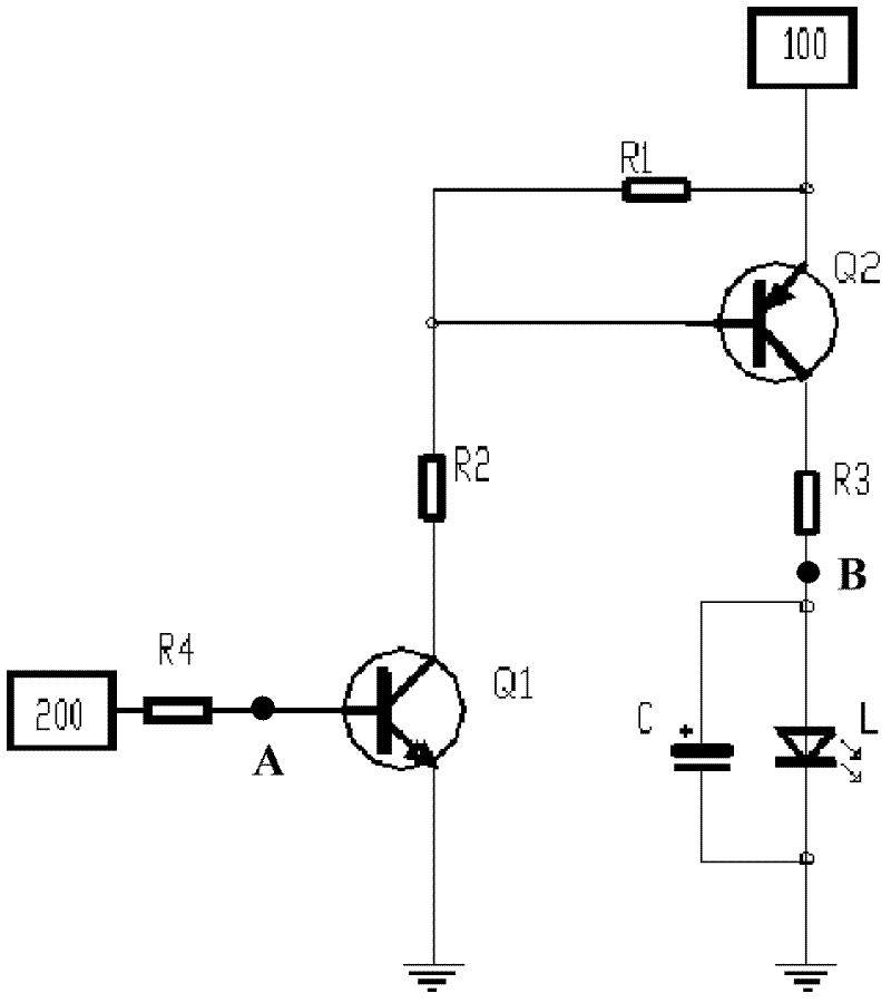
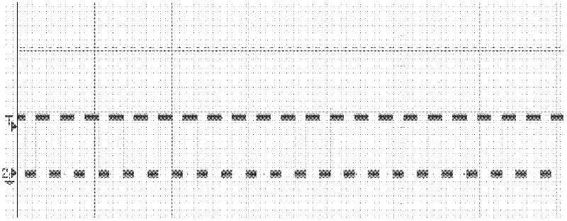
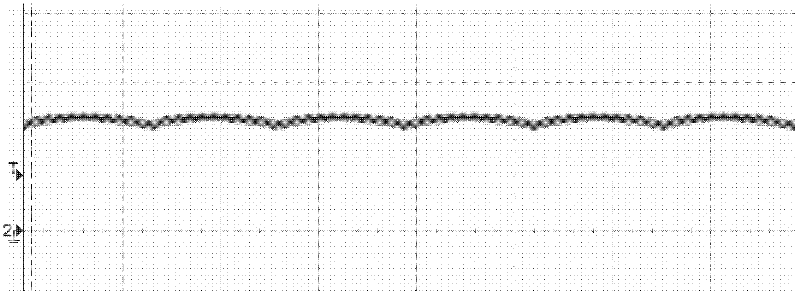
The invention provides a breath light control circuit, comprising a power supply, a first resistance and a second resistance which are connected in series, a first switching tube, a second switching tube, a third resistance, a fourth resistance and a controller, wherein one end of the first resistance is connected with the power supply, the collector of the first switching tube is connected with one end of the second resistance, and the emitter of the first switching tube is grounded; the base of the second switching tube is connected with a node between the first resistance and the second resistance, the emitter of the second switching tube is connected with the power supply; one end of the third resistance is connected with the collector of the second switching tube, the other end of the third resistance is connected with a breath light; one end of the fourth resistance is connected with the base of the first switching tube; and the controller is connected with the other end of the fourth resistance and is used for applying a PWM control signal to the first switching tube by virtue of the fourth resistance and gradually adjusting duty ratio of the PWM control signal according to a preset step size by taking a preset time as a period. The breath light control circuit provided by the invention has the advantages of simple design and low cost.

Description

technical field [0001] The invention relates to a non-portable lighting device or system, in particular to a control circuit for a breathing lamp. Background technique [0002] The breathing light device is applied to the terminal equipment. The brightness of the LED (Light Emitting Diode, light-emitting diode) in the device changes gradually from bright to dark under the control of the microcomputer, as if breathing. It can provide visual prompts on the terminal equipment and play a role. Very good visual decoration effect, has been widely used in various fields such as home appliances, mobile phones, computers, automobiles, etc. [0003] The breathing light products currently on the market usually use the following two methods to control LED lights: [0004] (1) Control the working of the breathing light through PWM (Pulse Width Modulation, Pulse Width Modulation) of high frequency (above 10KHz). The disadvantage of this method is that the main chip needed is relatively a...

Claims


Application Information

Patent Timeline
Patent Type & Authority Applications(China)
IPC IPC(8): H05B37/02
Inventor 孙超申在成刘富明
Owner HEFEI MIDEA REFRIGERATOR CO LTD
Learn More