Multifunctional adjustable puller

An adjustable and puller technology, which is applied in the direction of hand-held tools and manufacturing tools, can solve the problems of troublesome tool management, complicated operation, and many parts, so as to achieve safe and convenient assembly and use, improve drawing efficiency, and expand the scope of use. wide effect

Inactive Publication Date: 2012-03-21
SHANGHAI GAOQIAO SGPEC PETROCHEM ENG & CONSTR
View PDF8 Cites 1 Cited by
  • Summary
  • Abstract
  • Description
  • Claims
  • Application Information

AI Technical Summary

Problems solved by technology

[0003] In the process of using the commonly used puller, once the puller hook hooks the half coupling to be removed and is stressed, the puller's puller is easily displaced laterally and slides out, making the disassembly of the half coupling The work of the device cannot continue
Therefore, in the prior art, it is necessary to use iron wires to bind the drag hook and the half-coupling, or to fix the drag hook and the half-coupling by heating and welding auxiliary measures, but the effect is not ideal
[0004] Secondly, the pullers used in the prior art do not have flexible adjustment functions, and cannot be applied to the disassembly work of various specifications or different equipment. As a result, it is necessary to equip different specifications of equipment with different specifications of pullers when working on site. Pulling out the tool leads to complicated operations and troublesome tool management
[0005] Finally, the puller in the prior art has a complex structure and many parts, which is not easy to carry and repair and maintain

Method used


Image

  • Multifunctional adjustable puller
  • Multifunctional adjustable puller
  • Multifunctional adjustable puller

Examples


Embodiment 1

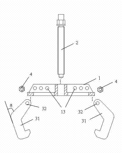
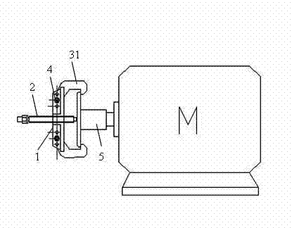
[0032] Such as figure 1 As shown, the multifunctional adjustable puller provided by the present invention includes: a die crossbeam 1 , a die bolt 2 and a die connector; wherein, the die connector is a die hook 31 .

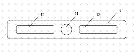
[0033] Such as figure 2 As shown, there is a threaded hole 11 vertically penetrating through the middle of the die beam 1 , the threaded hole 11 is matched with the die bolt 2 , and the die bolt 2 is passed through the threaded hole 11 .

[0034] In this embodiment, the drawing bolt 2 adopts a T-shaped screw.

[0035] At both ends of the threaded hole 11 , mounting holes 12 are vertically penetrating respectively, and the mounting holes 12 are elongated, and are used for respectively mounting the drawing hooks 31 .

[0036] please refer again figure 1 , within the length range of the installation hole 12 on the drawing beam 1 , a plurality of first positioning holes 13 are horizontally penetrated and sequentially arranged at intervals. In this embodiment, th...

Embodiment 2

[0050] The second embodiment is basically similar in structure to the multifunctional adjustable puller described in the first embodiment above, the only difference is that in this embodiment, the die connecting part is a long die screw 33 .

[0051] The top of the long drawing screw 33 is also provided with a third positioning hole matching the first positioning hole 13; the long drawing screw 33 is respectively installed in the mounting holes 12 on both sides of the drawing beam 1 , and use the bolt 4 to pass through one of the first positioning hole 13 and the third positioning hole, thereby connecting the long drawing screw 33 and the drawing beam 1 . In addition, the first positioning holes 13 fixed at different positions can be adjusted by adjusting the long drawing screws 33, thereby adjusting the opening between the long drawing screws at both ends of the puller, so that it is suitable for the disassembly of parts of different specifications and different equipment . ...


PUM


Abstract

The invention discloses a multifunctional adjustable puller which comprises a drawing die beam, a drawing die bolt and a drawing die connecting piece, wherein a threaded hole matched with the drawing die bolt vertically penetrates through the middle part of the drawing die beam; the drawing die bolt penetrates through in the threaded hole; the two ends of the threaded hole penetrate through a mounting hole vertically respectively; in the length range of the mounting hole on the drawing die beam, multiple first positioning holes penetrate horizontally and are sequentially arranged at intervals; and the drawing die connecting piece is a drawing die hook or drawing die long screw. The multifunctional adjustable puller provided by the invention has a simple structure, is safe and convenient to assemble and use, is suitable for dismantling various parts of different specifications or parts of different devices, has high pulling efficiency and long service life and has small possibility of unhooking.

Description

technical field [0001] The invention relates to a puller, in particular to a multifunctional adjustable puller. Background technique [0002] Modern petrochemical enterprises, large electric power enterprises, super large coal mining enterprises, etc., cannot do without the couplings connecting the original motors and equipment for the moving equipment. When encountering regular maintenance of equipment, repairing faults, dismantling machinery and equipment, etc., first remove the half coupling on the equipment shaft, or the half coupling on the motor, some are called counter wheels, and some are called back wheels. According to the process and regulations of the maintenance operation of the moving equipment, the operator needs to be equipped with a puller to remove the half coupling from the original motor or other moving equipment. [0003] In the process of using the commonly used puller, once the puller hook hooks the half coupling to be removed and is stressed, the pul...

Claims


Application Information

Patent Timeline
Patent Type & Authority Applications(China)
IPC IPC(8): B25B27/02
Inventor 陈根宝
Owner SHANGHAI GAOQIAO SGPEC PETROCHEM ENG & CONSTR
Why Eureka
Try Eureka