pneumatic tire

A technology for pneumatic tires and tires, applied in tire parts, tire tread/tread pattern, transportation and packaging, etc., can solve the problems of reduced handling stability, reduced lateral rigidity, reduced noise performance, etc. Rigidity, high drainage, and the effect of improving noise performance

Active Publication Date: 2015-09-09
SUMITOMO RUBBER IND LTD
View PDF4 Cites 0 Cited by
  • Summary
  • Abstract
  • Description
  • Claims
  • Application Information

AI Technical Summary

Problems solved by technology

[0003] However, in the case of forming such a linear circumferential narrow groove e, there is a problem that air column resonance occurs in the circumferential narrow groove e and the noise performance is degraded.
In addition, there is a tendency to reduce the lateral rigidity while maintaining the circumferential rigidity of the middle rib d, resulting in a decrease in steering stability.

Method used


Image

  • pneumatic tire
  • pneumatic tire
  • pneumatic tire

Examples


Embodiment Construction

[0030] Hereinafter, embodiments of the present invention will be described in detail.

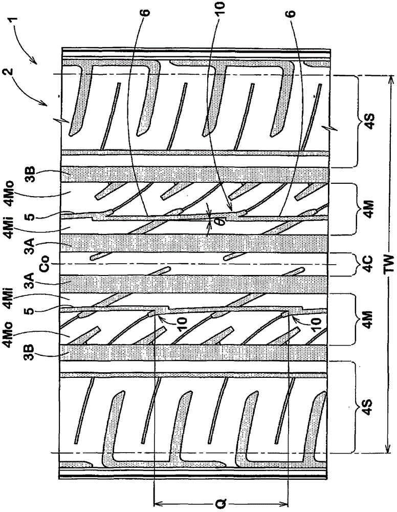
[0031] like figure 1 As shown, the pneumatic tire 1 of this embodiment has, on the tread portion 2 , a pair of inner circumferential main grooves 3A extending on both sides of the tire equatorial plane Co, and a pair of outer circumferential main grooves 3B arranged on both outer sides of the inner circumferential main grooves 3A. , thus the tread portion 2 is divided into the following five ribs, namely: the central rib 4C between the inner circumferential main grooves 3A, 3A, the middle rib between the inner circumferential main groove 3A and the outer circumferential main groove 3B 4M, 4M, and shoulder ribs 4S, 4S on the outer side in the tire axial direction than the outer circumferential main groove 3B.

[0032] Here, as the above-mentioned inner circumferential main groove 3A, one circumferential main groove extending on the tire equatorial plane Co may be used. In this case, the tr...


PUM


Abstract

PROBLEM TO BE SOLVED: To improve noise performance and driving stability without deteriorating drainage property. SOLUTION: Circumferential fine grooves extended in the tire circumferential direction are disposed on middle ribs each arranged between inner circumferential main grooves extended on the tire equatorial plane or on both side of the tire equatorial plane and outer circumferential main grooves arranged on both outer sides of the inner circumferential main grooves. Each of the circumferential fine grooves assumes a straight line shape or a circular arc shape extended in the circumferential direction at an angle θ of 0 to 25° with respect to the tire circumferential direction and is composed of a plurality of fine groove pieces each having a groove width smaller than the inner and outer circumferential main grooves. Fine groove pieces are connected with each other in the circumferential direction via a superimposition part having a width wider than the fine groove piece because end parts of the fine groove pieces adjoining in the circumferential direction are arranged side by side inside and outside the tire axial direction. COPYRIGHT: (C)2012,JPO&INPIT

Description

technical field [0001] The present invention relates to a pneumatic tire, and more particularly, to a pneumatic tire which suppresses a decrease in water drainage to a minimum, or maintains water drainage, and improves noise performance and steering stability. Background technique [0002] For example, pneumatic tires such as Figure 8 As shown, the inner circumferential main groove b provided on the tire equatorial plane Co or extending on both sides of the tire equatorial plane Co in the tread portion a and the outer circumferential main grooves c and c disposed on both outer sides of the inner circumferential main groove b , thereby forming a pneumatic tire in which the middle rib d is formed between the inner circumferential main groove b and the outer circumferential main groove c. In addition, generally, in order to improve drainage and ensure straight running stability while maintaining circumferential rigidity, the middle rib d is formed with circumferential narrow g...

Claims


Application Information

Patent Timeline
Patent Type & Authority Patents(China)
IPC IPC(8): B60C11/03B60C11/04B60C11/113
CPCB60C11/11B60C11/12B60C11/13B60C11/1369B60C19/002
Inventor 和春亮
Owner SUMITOMO RUBBER IND LTD
Why Eureka
Try Eureka