Shutter driving device of locomotive cooling system

A cooling system and driving device technology, applied to locomotives, etc., can solve problems such as high failure rate, backwardness, gas contained in oil and exhaust, etc., and achieve the effect of low failure rate and wide application range

Inactive Publication Date: 2012-03-21
CRRC DALIAN CO LTD
View PDF6 Cites 0 Cited by
  • Summary
  • Abstract
  • Description
  • Claims
  • Application Information

AI Technical Summary

Problems solved by technology

The current cooling system of diesel locomotives adopts the expansion and contraction of the hydrostatic oil cylinder and is equipped with a lever arm to control the opening and closing of the shutters, which is relatively backward, and the disadvantage is that it must be equipped with a hydrostatic oil system. If the cooling fan of the locomotive is not driven by a hydrostatic oil pump and an oil distribution motor system, the cooling louvers cannot be matched using the above scheme
Even if it is equipped with a hydrostatic oil pump oil distribution motor system, because the hydrostatic oil cylinder is prone to problems such as gas in the oil and difficulty in exhausting, sometimes the mechanism will be stuck, and the failure rate is relatively high

Method used


Image

  • Shutter driving device of locomotive cooling system
  • Shutter driving device of locomotive cooling system
  • Shutter driving device of locomotive cooling system

Examples


Embodiment Construction

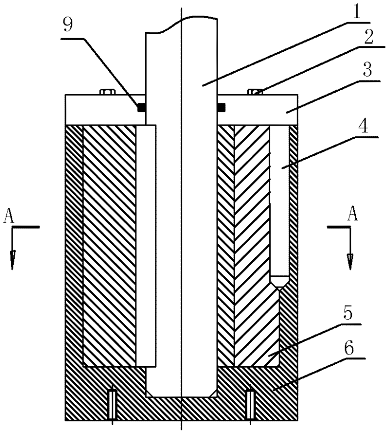
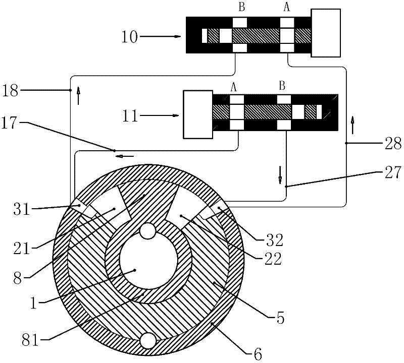
[0021] The working principle of the locomotive cooling system louver driving device of the present invention is to drive the pneumatic two-position rotary angle valve 12 through the wind pressure of the locomotive braking system to drive the louver to open and close.

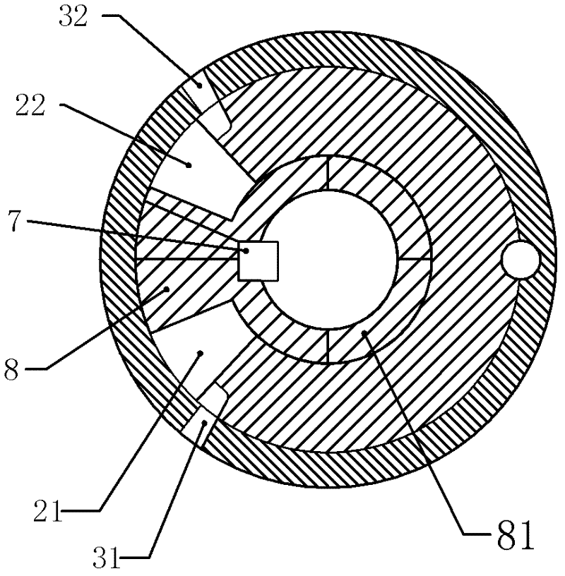
[0022] First, the structure and action principle of the pneumatic two-position rotary valve 12 are as follows. Such as figure 1 , figure 2 As shown, the pneumatic two-position rotary valve 12 includes a valve body, a drive shaft 1 at the center, and a drive vane 8 fixedly connected to the drive shaft 1. The valve body has a fan-shaped cavity, and the drive vane 8 moves in the fan-shaped cavity. The cavity is divided into the first air chamber 21 and the second air chamber 22 which are respectively sealed. The first air hole 31 corresponding to the position of the first air chamber 21 and the corresponding hole 31 to the position of the second air chamber 22 are opened on the valve body. The second air hole 32...


PUM


Abstract

The invention relates to a shutter driving device of a locomotive cooling system. The shutter driving device which comprises rotating shutter shafts is characterized in that: the rotating shutter shafts which drive shutter fan leaves to rotate are driven by a pneumatic two-position rotating valve; the pneumatic two-position rotating valve comprises a valve body, a driving shaft at the center of the pneumatic two-position rotating valve, and a driving leaf which is fixedly connected with the driving shaft; the valve body has a fan-shaped cavity; the driving leaf moves in the fan-shaped cavity and divides the fan-shaped cavity into a first air cavity and a second air cavity which are respectively sealed; and the valve body is provided with a first pore and a second pore which respectively correspond with the first air cavity and the second air cavity and are respectively communicated with an air inlet tube, and an air outlet tube. The air administration and the air venting of the two air cavities are controlled by solenoid valves to drive the driving leaf to move, so the driving leaf drives the rotating shutter shafts to open or close a shutter. The device of the invention, which directly takes the blast of a locomotive brake system as a working medium, doe not relates to a problem of venting needed by oil, so the failure rate is low, thereby the device which can be applied to locomotives with air braking has a versatility when the device is applied to railroad locomotives.

Description

technical field [0001] The invention relates to a locomotive cooling system, in particular to a shutter driving device for the locomotive cooling system. Background technique [0002] The cooling system of the existing diesel locomotive uses a cooling fan to cool the radiator. There are louvers installed between the cooling fan and the radiator. When the cooling fan needs to be started, the louvers are opened, otherwise the louvers are closed. Therefore, the louvers need to be opened and closed as needed. close. The current cooling system of diesel locomotives adopts the expansion and contraction of the hydrostatic oil cylinder and is equipped with a lever arm to control the opening and closing of the shutters, which is relatively backward, and the disadvantage is that it must be equipped with a hydrostatic oil system. If the cooling fan of the locomotive is not driven by a hydrostatic oil pump and an oil distribution motor system, the cooling louvers cannot be matched usin...

Claims


Application Information

Patent Timeline
Patent Type & Authority Applications(China)
IPC IPC(8): B61C17/04
Inventor 颜光耀于克俊董志忠
Owner CRRC DALIAN CO LTD
Why Eureka
Try Eureka