
Drilling machine and method, controller and system for monitoring clamping and joint of drilling rods of drilling machine

A technology for detecting controllers and controllers, which is applied in the automatic control system of drilling, drilling equipment, earthwork drilling, etc., can solve the problem of low accuracy, and achieve the effect of less external interference and accurate measurement results.

Active Publication Date: 2012-03-21
ZOOMLION HEAVY IND CO LTD
View PDF5 Cites 14 Cited by
  • Summary
  • Abstract
  • Description
  • Claims
  • Application Information

AI Technical Summary

Problems solved by technology

In addition, there are currently some monitoring methods and devices for the "rod" state, but when using these monitoring methods for monitoring, there are many factors that affect the monitoring results, so the accuracy is not high

Method used


Image

  • Drilling machine and method, controller and system for monitoring clamping and joint of drilling rods of drilling machine
  • Drilling machine and method, controller and system for monitoring clamping and joint of drilling rods of drilling machine
  • Drilling machine and method, controller and system for monitoring clamping and joint of drilling rods of drilling machine

Examples


Embodiment Construction

[0030] Specific embodiments of the present invention will be described in detail below in conjunction with the accompanying drawings. It should be understood that the specific embodiments described here are only used to illustrate and explain the present invention, and are not intended to limit the present invention.

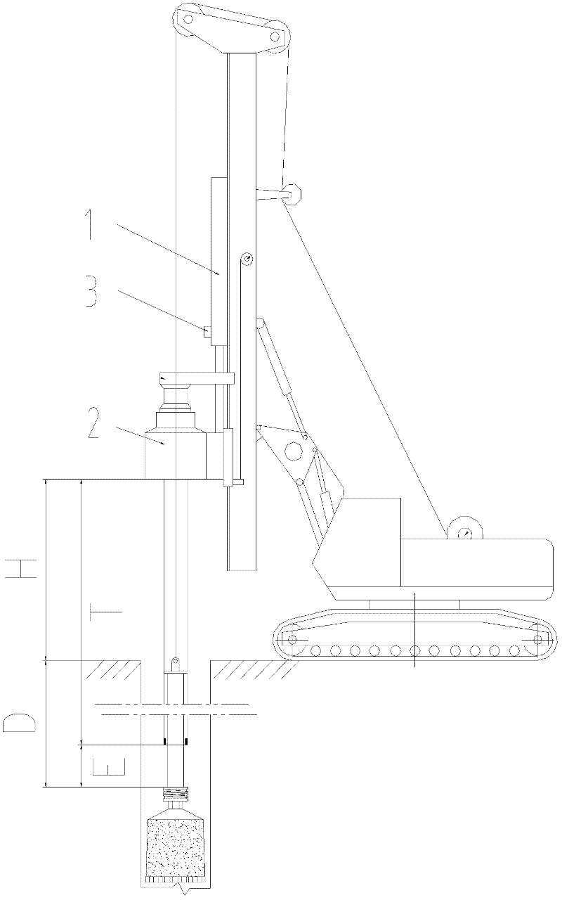
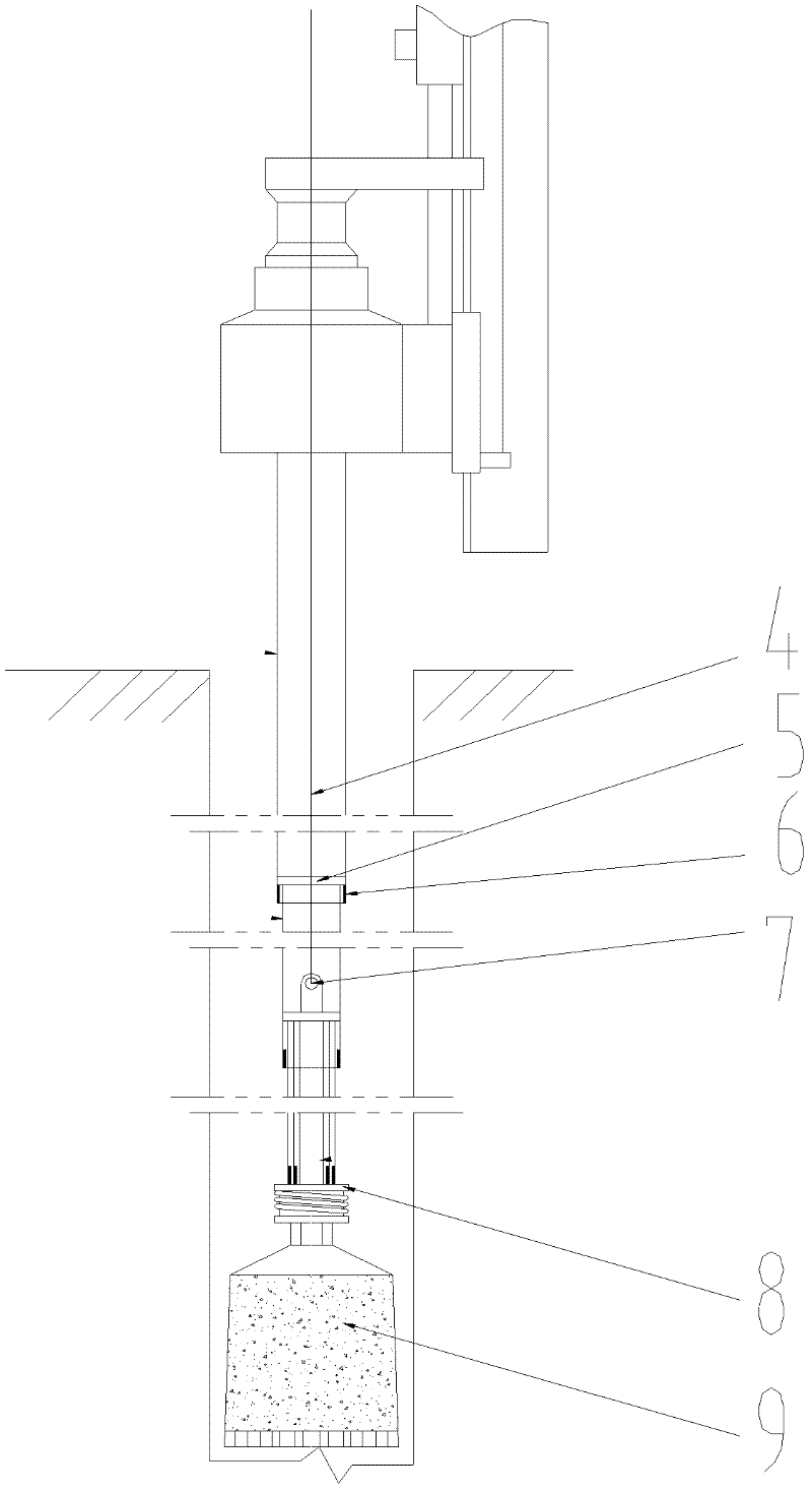
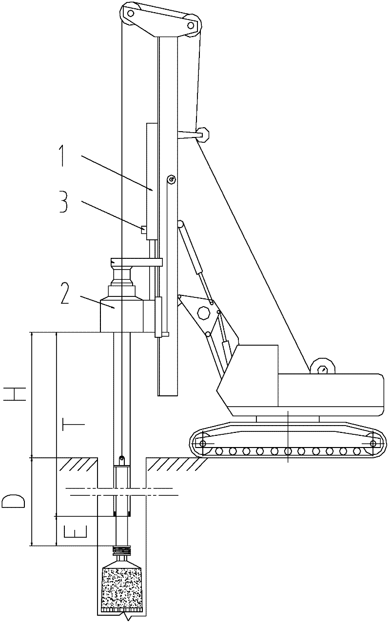
[0031] In order to facilitate the understanding of the technical solution of the present invention, the working conditions of each part of the drilling rig when lifting the drill pipe are firstly introduced.

[0032] When the drill pipe is working, the pressurizing device 1 of the drilling rig is used to provide pressure for the drill pipe. When lifting the drilling rod, the outermost drilling rod falls on the power head 2 through the traveling frame, and its weight is borne by the power head. The power head is connected with the pressurizing device 1, so the weight borne by the power head is transmitted to the pressurizing device 1 for bearing. Except for the...


PUM


Abstract

The invention discloses a method for monitoring the clamping and the joint of drilling rods of a drilling machine. The drilling machine comprises a plurality of sections of drilling rods, a power head (2) and a pressurizing device (1); the power head (2) is used for pressurizing the drilling rods; the pressurizing device (1) is used for pressurizing the power head (2); and the drilling rods comprises the drilling rods from the 1st section to the Nth section from outside to inside, wherein i can be 2, 3, ... and N. The method comprises the following step: detecting to confirm whether the lifted drilling rod is the i-section drilling rod or not, and detecting to find whether the actual tension of the pressurizing device (1) at the moment is fi or not; comparing the actual tension fi with the preset rated tension Fi of the i-section drilling rod; and confirming that the i-section drilling rod is blocked and jointed when the actual tension fi is less than the rated tension Fi. In addition, the invention further discloses a monitoring controller and a monitoring system for implementing the method and the drilling machine with the monitoring system. Due to the adoption of the technical scheme of the invention, the external interference to the monitoring of the actual tension of the pressurizing device is less, and the measuring result is more accurate.

Description

technical field [0001] The invention relates to the field of engineering machinery, in particular to a drilling rig monitoring method, a controller, a monitoring system and a drilling rig with the monitoring system. Background technique [0002] At present, the application of rotary drilling rigs is becoming more and more extensive. Rotary drilling rigs usually use telescopic drill pipes. During the lifting operation of the telescopic drill pipes, the telescopic drill pipes will be lifted section by section from the inside to the outside. However, due to many uncontrollable reasons, the drill pipe will be lifted and shrunk in an abnormal sequence. As long as any outer section drill pipe shrinks before its inner section drill pipe, it proves that there is a stuck or stuck between it and the inner section. Engagement, this is called "with rod". [0003] In this "with rod" state, when the drill pipe is lifted to a certain height, if the "with rod" state is released due to rea...

Claims


Application Information

Patent Timeline
Patent Type & Authority Applications(China)
IPC IPC(8): E21B44/00
Inventor 李志杰罗建利孙涛
Owner ZOOMLION HEAVY IND CO LTD
Learn More