
Zoom optical system and shooting device

An optical system and lens group technology, applied in optics, optical components, components of TV systems, etc., can solve the problems of difficulty in miniaturization and cost reduction, large amount of movement of the second lens group, insufficient chromatic aberration correction, etc. Achieve the effect of less image clarity, small F value, and good chromatic aberration correction

Inactive Publication Date: 2012-03-21
FUJIFILM CORP
View PDF7 Cites 6 Cited by
  • Summary
  • Abstract
  • Description
  • Claims
  • Application Information

AI Technical Summary

Problems solved by technology

However, in the CCTV field, since the differentiation of CCTV cameras and mounting lenses is advancing, it is difficult to apply the above-mentioned technology in the field of digital cameras, and as a result, it is necessary to suppress the occurrence of color bleeding by the lens system itself.
[0010] In the conventionally known devices described in Patent Documents 1 to 3, the correction of chromatic aberration is insufficient, or the F value is too large when used as a CCTV at the wide-angle end.
In addition, in the device described in Patent Document 4, since the first lens group is composed of four pieces, the outer diameter of the first lens group is large, and the movement amount of the second lens group is relatively large, so it is relatively small and low in cost. difficulty

Method used


Image

  • Zoom optical system and shooting device
  • Zoom optical system and shooting device
  • Zoom optical system and shooting device

Examples


Embodiment 1

[0134] Example 1 Basic Lens Data

[0135]

[0136]

[0137] Table 2

[0138] Embodiment 1 and data related to variable power

[0139] wide-angle end

middle

telephoto end

Variable 1

1.041

16.622

26.261

Variable 2

26.476

10.868

1.299

Variable 3

12.937

8.392

13.194

Variable 4

10.000

14.545

9.743

f

8.159

25.293

77.756

FNo.

1.70

1.93

2.18

56.74

18.23

5.82

[0140] table 3

[0141] Embodiment 1 Aspherical data

[0142]

[0143]

[0144] Table 4

Embodiment 2

[0145] Example 2 Basic Lens Data

[0146]

[0147]

[0148] table 5

[0149] Embodiment 2 and data related to variable power

[0150] wide-angle end

middle

telephoto end

Variable 1

0.688

16.177

26.222

Variable 2

26.553

11.064

1.019

Variable 3

10.574

5.983

10.915

Variable 4

10.000

14.591

9.659

f

8.051

24.958

76.725

FNo.

1.67

1.99

2.22

58.43

18.45

5.88

[0151] Table 6

[0152] Embodiment 2 Aspherical data

[0153]

[0154] Table 7

Embodiment 3

[0155] Embodiment 3 basic lens data

[0156]

[0157]

[0158] Table 8

[0159] Embodiment 3 and data related to variable power

[0160] wide-angle end

middle

telephoto end

Variable 1

1.231

16.590

26.440

Variable 2

26.340

10.981

1.131

Variable 3

13.074

8.621

13.477

Variable 4

10.000

14.453

9.597

f

8.064

25.000

76.854

FNo.

1.67

1.99

2.22

58.43

18.45

5.88

[0161] Table 9

[0162] Embodiment 3 Aspherical data

[0163]

[0164] Table 10


PUM


Abstract

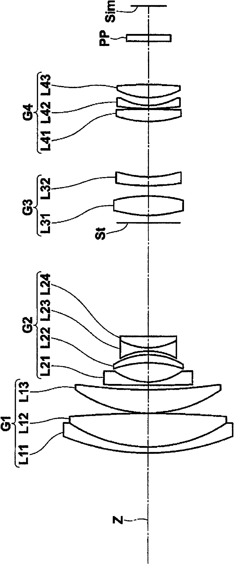
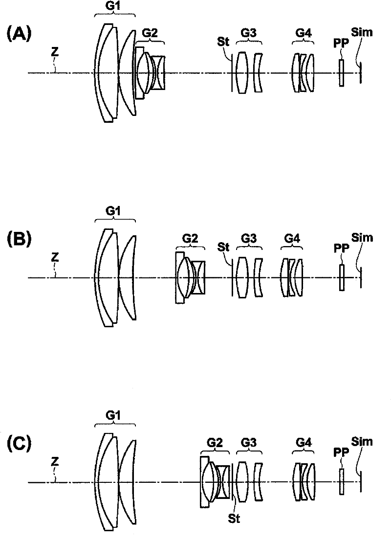
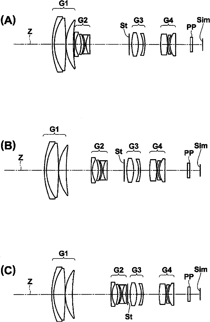
The invention provides a zoom optical system and a shooting device. The zoom optical system realizes small size, low cost, relatively low F value, good chrominance correction and high optical performance. The zoom optical system successively comprises, from the object side, a positive first lens group (G1) which is fixed during the zooming, a second lens group (G2) which is moved along an optical axis so as to perform the zooming, a diaphragm which is fixed during the zooming, a positive third lens group (G3) which is fixed during the zooming, and a positive fourth lens group (G4) which corrects the image plane position and focuses along with the zooming operation. The second lens group (G2) successively comprises, from the object side, a negative lens, a positive meniscus lens with a concave surface being oriented to the object side, a biconcave lens and a positive lens. The zoom optical system is configured in such a manner to satisfy the prescribed conditions related to the focal length of the second lens group (G2), the Abbe number of the positive meniscus lens of the second lens group (G2) and the amount of movement of the second lens group (G2) during the zooming from the wide end to the tele end.

Description

technical field [0001] The present invention relates to a variable magnification optical system and an imaging device. More specifically, it relates to a variable magnification optical system that can be used in video cameras, electronic still cameras, etc., and is especially suitable for use as a surveillance camera, and a device equipped with the variable magnification optical system. camera device. Background technique [0002] Currently, CCTV (Closed- circuit Television) with zoom optical system. In this variable power optical system for CCTV, in terms of the four-group configuration, there are many advantages such as the simplification of the lens barrel and the variable power mechanism and the ease of operation, and many have been proposed (for example, refer to the following patent documents 1 to 1). 4). [0003] Patent Document 1: JP-A-2003-98434 [0004] Patent Document 2: JP-A-2004-325566 [0005] Patent Document 3: JP-A-2006-113387 [0006] Patent Document 4...

Claims


Application Information

Patent Timeline
IPC IPC(8): G02B15/173H04N5/225
Inventor 大野和则
Owner FUJIFILM CORP
Learn More