
Decentration optical system, and image display apparatus and imaging apparatus incorporating the same

An image display device and optical system technology, which is applied to the parts, optics, and optical components of the TV system, can solve the problems of time-consuming assembly and adjustment, and problems with water resistance and resistance, and achieve the effect of high degree of freedom in configuration

Active Publication Date: 2012-03-21
OLYMPUS CORP
View PDF10 Cites 5 Cited by
  • Summary
  • Abstract
  • Description
  • Claims
  • Application Information

AI Technical Summary

Problems solved by technology

Furthermore, assembly and adjustment are labor-intensive, and there are problems with the durability of the device, such as water resistance.

Method used


Image

  • Decentration optical system, and image display apparatus and imaging apparatus incorporating the same
  • Decentration optical system, and image display apparatus and imaging apparatus incorporating the same
  • Decentration optical system, and image display apparatus and imaging apparatus incorporating the same

Examples


Embodiment 1

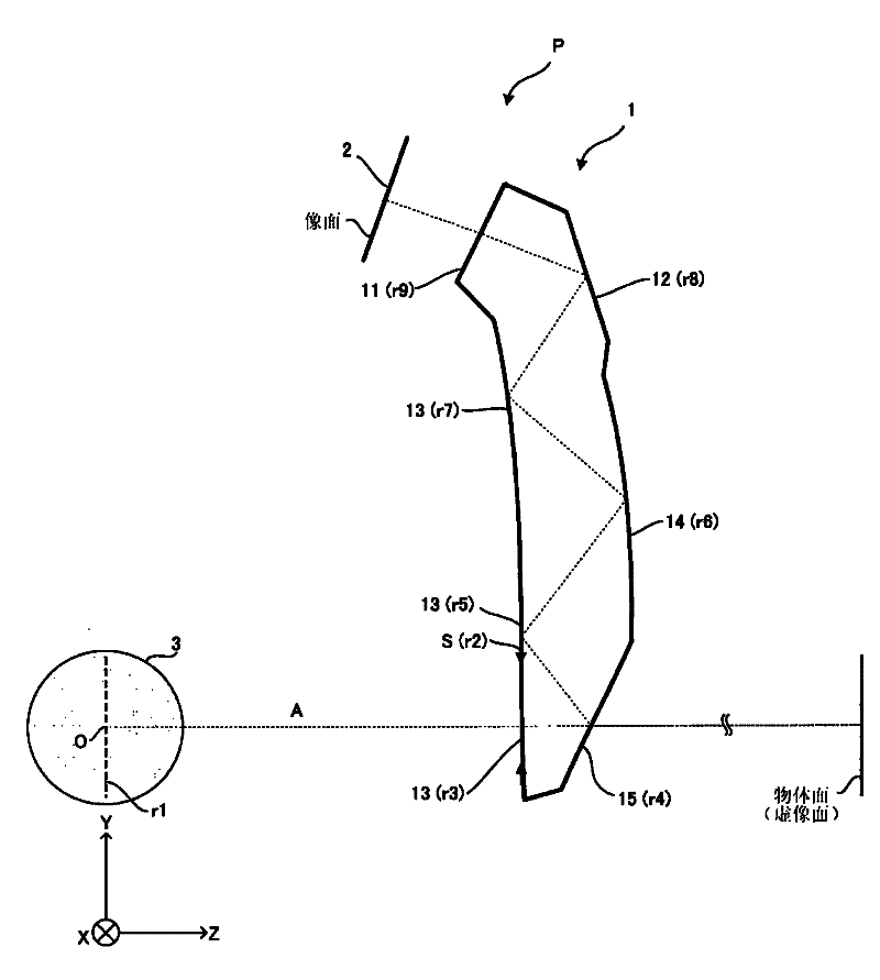
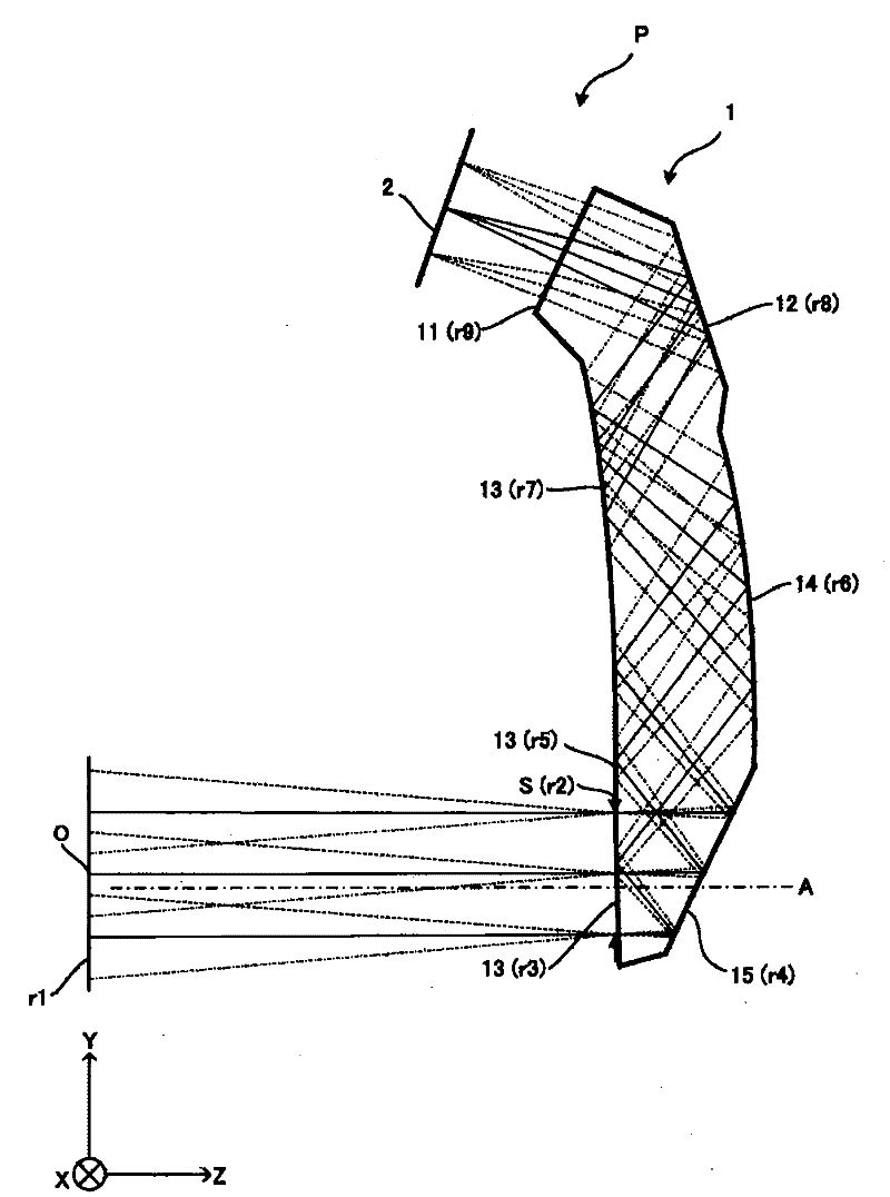
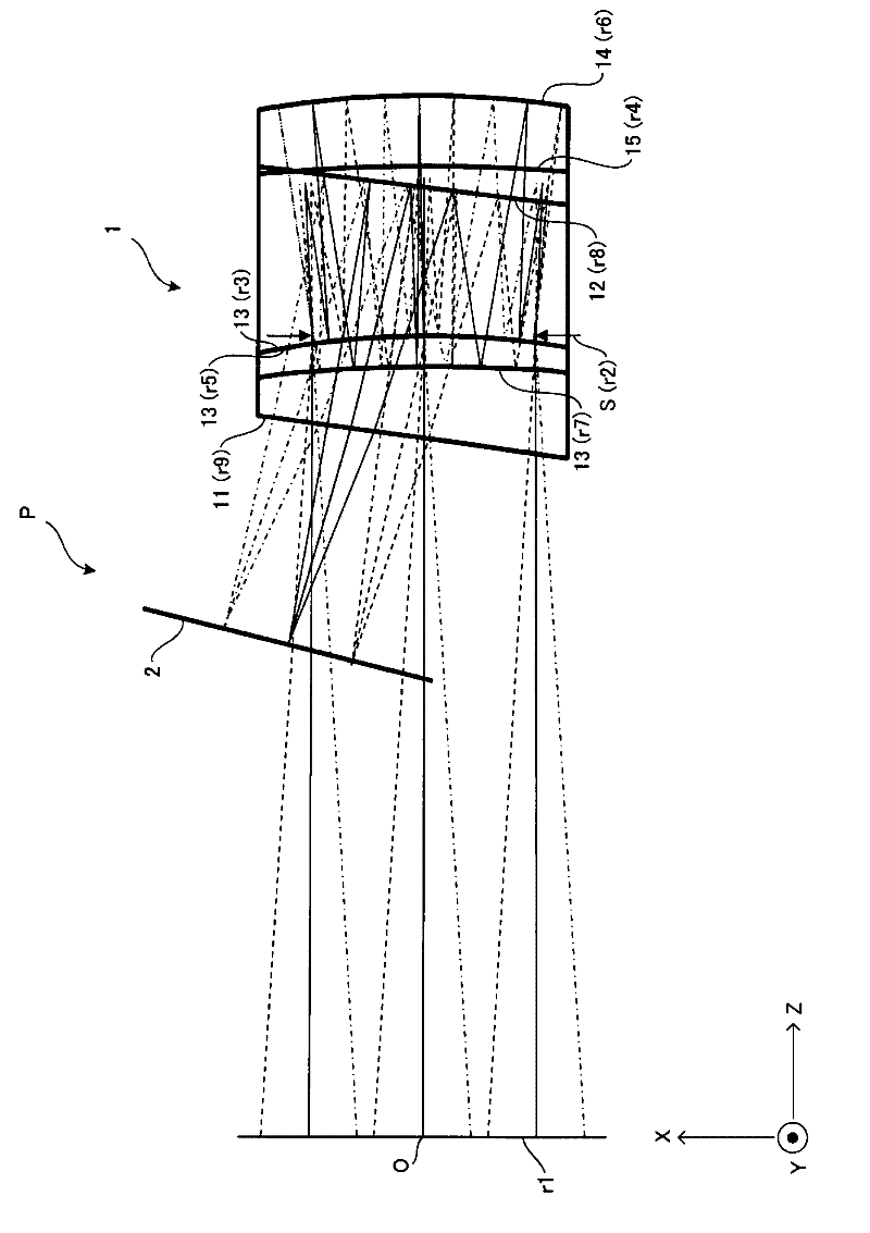
[0173] The image display device P of Embodiment 1 has a decentering optical system 1 and an image display element 2 .

[0174] The decentered optical system 1 uses five surfaces to form an optical surface having an optical function. The first surface 11 is disposed opposite to the image display element 2 and has a primary transmission function. In addition, the second surface 12 is disposed on the opposite side of the image display element 2 with respect to the first surface 11, and has a primary internal reflection effect. The third surface 13 faces the second surface 12, the fourth surface 14, and the fifth surface 15 described later, is arranged on the side of the image display element 2, and has a secondary internal reflection function and a primary transmission function.

[0175] The fourth surface 14 is opposed to the third surface 13, is arranged on the side opposite to the image display element 2, and has a primary internal reflection effect. The fifth surface 15 is ...

Embodiment 2

[0180] The image display device P of Example 2 has a decentering optical system 1 and an image display element 2 .

[0181] The decentered optical system 1 uses five surfaces to form an optical surface having an optical effect. The first surface 11 is disposed opposite to the image display element 2 and has a primary transmission function. In addition, the second surface 12 is arranged on the opposite side of the image display element 2 with respect to the first surface 11, and has a primary internal reflection effect. The third surface 13 faces the second surface 12, the fourth surface 14, and the fifth surface 15 described later, is arranged on the side of the image display element 2, and has a secondary internal reflection function and a primary transmission function.

[0182] The fourth surface 14 is opposed to the third surface 13, is arranged on the side opposite to the image display element 2, and has a primary internal reflection effect. The fifth surface 15 is dispo...


PUM


Abstract

The invention provides a decentration optical system comprising at least five optical surfaces. The optical surfaces are each decentered with respect to an axial chief ray in the Y-Z plane in the XYZ coordinate space, and at least one surface is decentered in the X-Z plane orthogonal to the Y-Z plane. At least two of the multiple optical surfaces are rotationally asymmetric surfaces, and at least one of the at least two rotationally asymmetric surfaces is a rotationally asymmetric surface having an X odd-numbered degree term.

Description

technical field [0001] The present invention relates to an optical device such as a decentered optical system using a rotationally asymmetric plane, an image display device using the decentered optical system, and an imaging device. Background technique [0002] Conventionally, an optical system using a prism having a plurality of optical surfaces as an observation image display element is known. In such a prism, the light emitted from the display element enters the prism, is reflected inside the prism, exits the prism, and reaches the observer's eyeball, whereby the image can be observed as a magnified virtual image. [0003] As an optical system for observing such an image, Patent Document 1 proposes an optical system based on a prism that forms a primary image via at least three reflecting surfaces and projects it to the eyeball, and Patent Documents 2 and 3 propose a hologram element arrangement. In the optical system of the eyeglass lens part, etc. [0004] In additio...

Claims


Application Information

Patent Timeline
Patent Type & Authority Applications(China)
IPC IPC(8): G02B27/01G02B27/02G02B6/00H04N5/225
CPCH04N5/2254G02B13/18G02B27/0172G02B17/086G02B2027/0178G02B2027/011
Inventor 高桥浩一
Owner OLYMPUS CORP
Learn More