Control system and control method for dynamic reactive power compensator

A control system and compensator technology, applied in reactive power compensation, reactive power adjustment/elimination/compensation and other directions, can solve the problems of large compensation capacity, slow response speed, and dynamic reactive power compensation speed that cannot meet the requirements, etc. To achieve the effect of reducing the capacity of the device and increasing the compensation capacity

Active Publication Date: 2012-03-21
CHINA NAT OFFSHORE OIL CORP +1
View PDF3 Cites 11 Cited by
  • Summary
  • Abstract
  • Description
  • Claims
  • Application Information

AI Technical Summary

Problems solved by technology

[0004] However, when implementing the control methods of these dynamic var compensators, that is, the conventional voltage control inner loop and reactive power control inner loop, although it has certain positive significance for the start-up of large motors in small grids, there are still deficiencies.
This is because although its voltage control can sense the bus voltage drop when the large motor starts and inject a certain amount of reactive power compensation, the response speed of the bus voltage is slower than the sudden increase of the reactive power of the motor, resulting in the speed of dynamic reactive power compensation up to It does not meet the requirements, and the control through simple voltage regulation may require a large compensation capacity; while the response speed of conventional reactive power control is slower, and it cannot even compensate for the sudden increase in reactive power caused by the start-up of large motors.

Method used


Image

  • Control system and control method for dynamic reactive power compensator
  • Control system and control method for dynamic reactive power compensator
  • Control system and control method for dynamic reactive power compensator

Examples


Embodiment 1

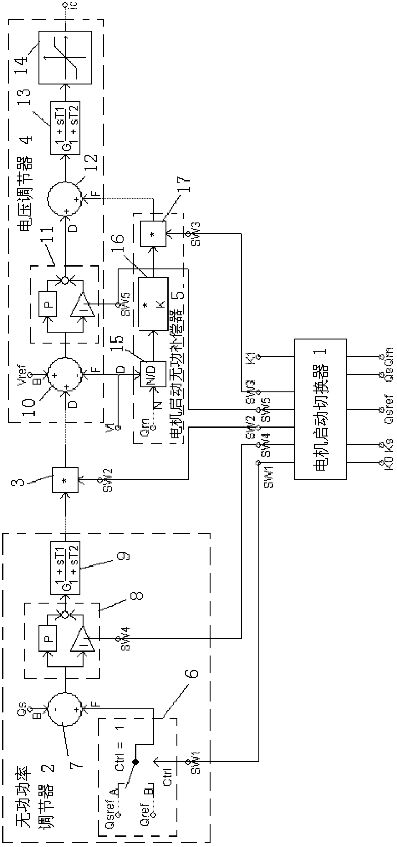
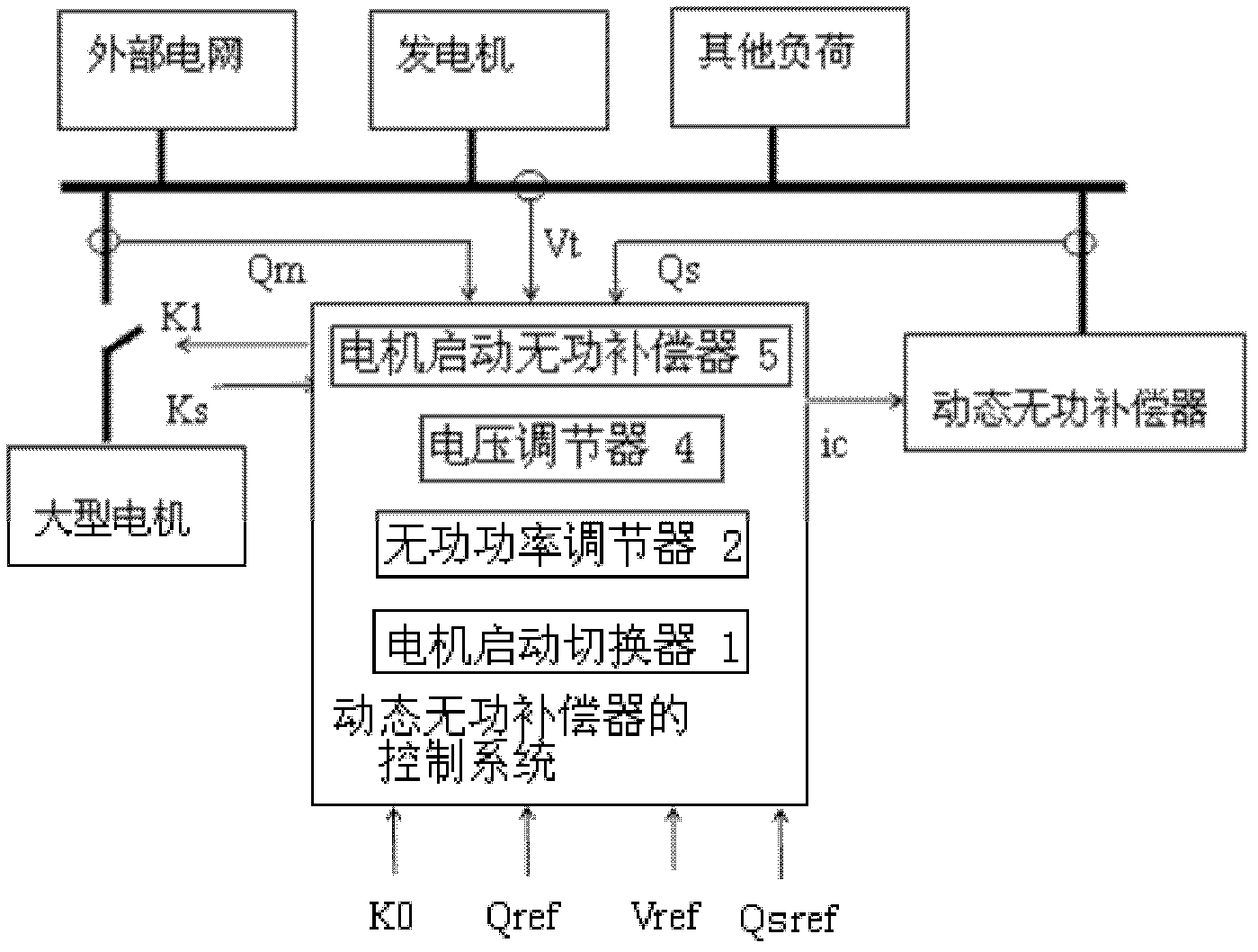
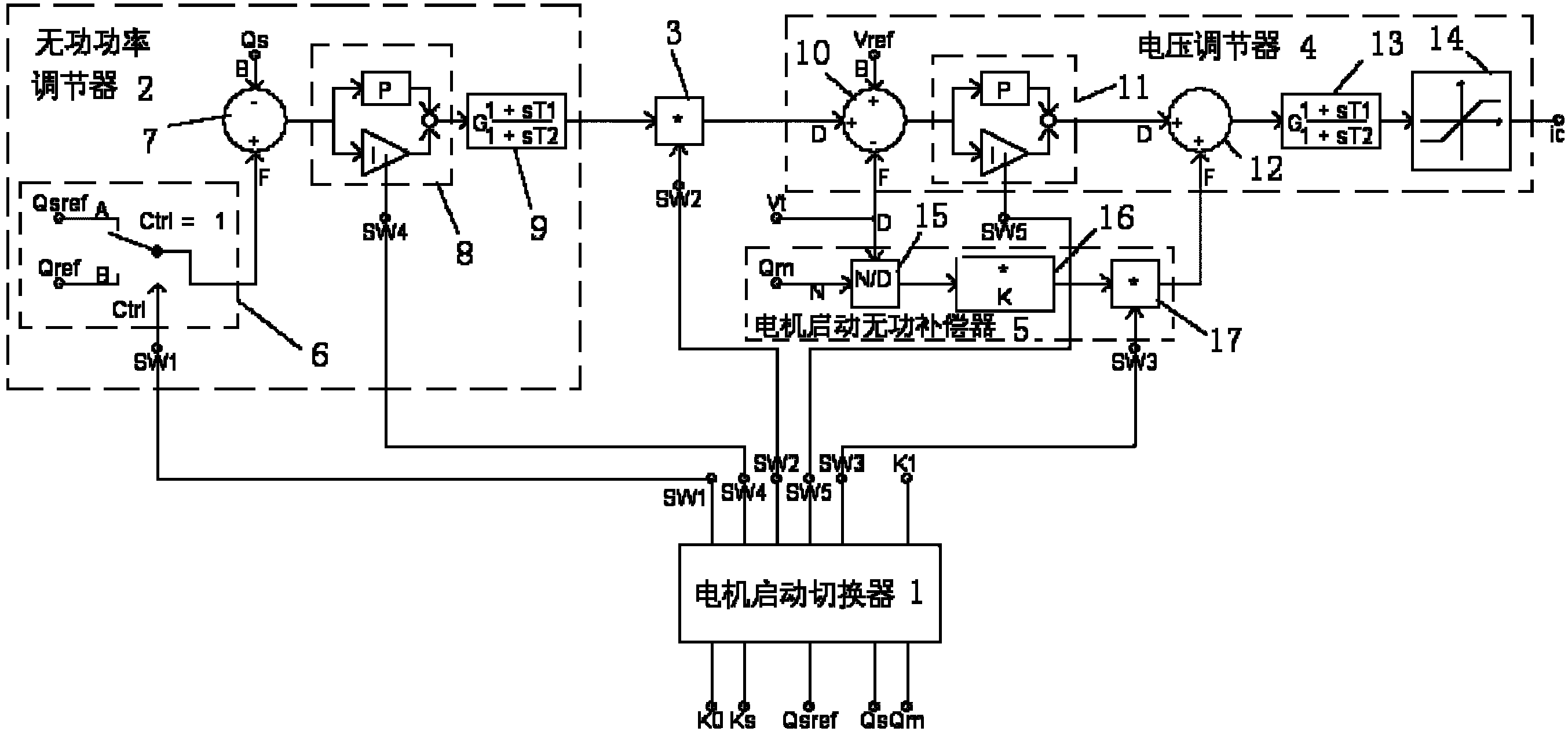
[0031] Embodiment 1: as figure 2 As shown, for a small power grid with a large asynchronous motor directly started, the dynamic reactive power compensator control and control method of the present invention will be designed and implemented according to the following steps:

[0032] 1) Capacity design of dynamic reactive power compensator. Firstly, determine the reactive power demand for direct start-up of large asynchronous motors. Generally speaking, the reactive power absorbed by the large asynchronous motors can reach 5 to 7 times the rated power (some asynchronous motors may even reach 8 to 10 times the rated power). The specific parameters are related to the load conditions. The maximum reactive power demand for motor startup in practical applications can be determined by several methods such as on-site testing, simulation analysis, and approximate estimation.

[0033] In the present invention, the reactive power adjustment range of the dynamic reactive power compensato...


PUM


Abstract

The invention relates to a control system and a control method for a dynamic reactive power compensator. The control system comprises a motor starting switcher which is connected to the input end of a large asynchronous motor, wherein a first path of switching signals and a fourth path of control signals output by the motor starting switcher are input to a reactive power regulator; the output endof the reactive power regulator is connected with a voltage regulator by a switcher; the on / off of the switcher is controlled by a second path of switching signals output by the motor starting switcher; a third path of switching signals output by the motor starting switcher are input into a motor starting reactive power compensator to control the on / off of the motor starting reactive power compensator and the voltage regulator; and reactive power signals output by the motor starting reactive power compensator are input into the voltage regulator, and the voltage regulator performs rapid dynamic reactive power regulation on the dynamic reactive power compensator under the control of a fifth path of control signals output by the motor starting switcher according to received reactive power output by the reactive power regulator and the reactive power signals. The control system and the control method can be widely applied in the field of motor and power system control.

Description

technical field [0001] The present invention relates to a control system of a dynamic var compensator and its control method in the field of motor and power system control, in particular to a control system and its control of a dynamic var compensator used to support the direct start of a large asynchronous motor method. Background technique [0002] In practical applications, there are some power grids with small scale, relatively weak electrical connections and sensitive to load shocks, such as power transmission terminals of remote radioactive power grids and power systems with small total installed capacity such as offshore oil field power grids. Taking a typical offshore oilfield power grid as an example, it is usually composed of several platform power stations connected to each other through long-distance submarine cables. Large asynchronous motor loads necessary for offshore oilfield development, such as water injection pumps, are installed. The capacity of the moto...

Claims


Application Information

Patent Timeline
Patent Type & Authority Applications(China)
IPC IPC(8): H02J3/18
CPCY02E40/30
Inventor 王建丰魏澈谢小荣黄业华刘国锋张强向守安刘皓胡鹏戴国华昝智海
Owner CHINA NAT OFFSHORE OIL CORP
Why Eureka
Try Eureka