Elevator self-help system

An elevator system and elevator technology, applied in elevators, transportation and packaging, etc., can solve the problems that users cannot effectively save themselves

Inactive Publication Date: 2012-03-28
SHANGHAI WEIPINLAI ELECTROMECHANICAL TECH
View PDF6 Cites 5 Cited by
  • Summary
  • Abstract
  • Description
  • Claims
  • Application Information

AI Technical Summary

Problems solved by technology

[0005] The technical problem to be solved by the present invention is to overcome the defect that the user cannot effectively save himself when the elevator fails in the prior art, and provides an elevator self-rescue system. By adding a system for controlling the brake, the user can manually control the The elevator descends to the bottom level area of ​​the elevator shaft, so that users can quickly get out of trouble

Method used


Image

  • Elevator self-help system
  • Elevator self-help system
  • Elevator self-help system

Examples


no. 1 example

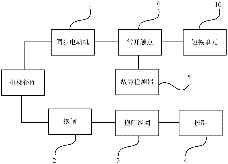
[0024] like figure 1 As shown, the elevator self-rescue system of this embodiment includes a synchronous motor 1 , a brake 2 , a brake coil 3 , a button 4 , a fault detector 5 , a normally open contact 6 and a shorting unit 10 .

[0025] The synchronous motor 1 is electrically connected to the short-circuit unit 10 through the normally open contact 6, and the short-circuit unit 10 is used to short-circuit the motor, and the brake coil 3 is connected to the brake 2 is connected and when the brake coil 3 is turned on, the brake 2 is opened, and the elevator car starts to move at this time, otherwise the brake 2 brakes the elevator car, and the elevator is in a static state. In this embodiment, the release action of the brake 2 is realized by controlling the brake coil in the brake 2 .

[0026] The brake coil 3 is also connected to the button 4. When the user presses the button 4, the button 4 is connected to the brake coil 3, and the loop formed makes the brake coil 3 also cond...

no. 2 example

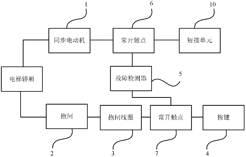
[0038] like figure 2 As shown, the difference between this embodiment and the first embodiment is that the elevator self-rescue system in this embodiment further includes a normally open contact 7, and the normally open contact 7 is connected in series with the brake coil 3 and the button between 4.

[0039] When the elevator fails, the fault detector 5 also closes the normally open contact 7 , so that a path is formed between the brake coil 3 and the button 4 . At this time, the user can make the connection between the button 4 and the brake coil 3 to release the brake 2, so that the elevator car enters the leveling area, which is convenient for the user's self-rescue.

[0040] In this embodiment, the brake coil 3 and the button 4 are isolated by the normally open contact 7, so as to prevent the user from misoperation when the elevator is running normally, that is, when the elevator is running normally, the user cannot control the button 4 The brake coil 3 is used to relea...

no. 3 example

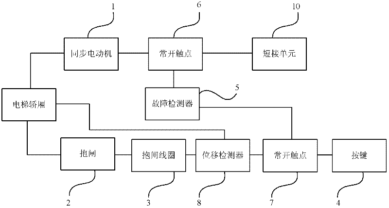
[0042] like image 3 As shown, the difference between this embodiment and the second embodiment is that the elevator self-rescue system in this embodiment further includes a displacement detector 8, which is used to detect whether the car of the elevator reaches the bottom of the elevator shaft or top.

[0043] In this embodiment, the displacement detector 8 is arranged between the normally open contact 7 and the brake coil 3. In addition, the user can also connect the displacement detector 8 with other components according to the design and structure of the elevator system. For example, the displacement detector 8 is arranged between the normally open contact 7 and the button 4 and the like.

[0044] When the elevator fails, when the displacement detector 8 does not detect that the car of the elevator reaches the bottom or top of the elevator shaft, the brake coil 3 and the displacement detector 8 are conductive, so the brake coil 3 Release the brake 2, so the user can rele...


PUM


Abstract

The invention discloses an elevator self-help system which comprises a motor and a band-type brake used for an elevator system, wherein the motor is used for driving a lift car; the band-type brake is used for braking the lift car; the elevator self-help system also comprises a short circuit unit, a band-type brake releasing unit, a band-type brake controlling unit, a first normally open contact unit and a fault detection unit, wherein the motor is electrically connected with the short circuit unit through the first normally open contact unit; the short circuit unit is used for connecting the motor in short circuit; the band-type brake controlling unit is electrically connected with the band-type brake releasing unit and is used for controlling the band-type brake releasing unit to release the band-type brake; and the fault detection unit is used for controlling the closing and opening of the first normally open contact unit through detecting whether the elevator system breaks down or not. The elevator system in the invention enables a user to control the elevator to descend to the bottom of an elevator shaft leveling zone, thereby enabling the user to rapidly escape from predicament.

Description

technical field [0001] The invention relates to an elevator self-rescue system, in particular to a self-rescue system for trapped persons when the elevator fails. Background technique [0002] When the elevator in the existing market breaks down, the elevator may stop at the non-leveling area in the elevator shaft and cannot run. At this time, it is usually necessary for professional elevator maintenance personnel to rush to the elevator to carry out rescue after being notified, and wait for the elevator. The maintenance process often takes 30 minutes to 1 hour, which causes great psychological adverse effects on the trapped passengers. [0003] Especially when a home elevator fails, because the elevator is located in the user's home, once the elevator fails and traps people, rescuers have to break in or contact relatives to open the door, causing great inconvenience to rescue and maintenance work. [0004] In addition, if the trapped person forcibly opens the elevator door...

Claims


Application Information

Patent Timeline
Patent Type & Authority Applications(China)
IPC IPC(8): B66B5/02
Inventor 洪浩王伟峰
Owner SHANGHAI WEIPINLAI ELECTROMECHANICAL TECH
Why Eureka
Try Eureka