Supercharge Your Innovation With Domain-Expert AI Agents!

Passive locking hydraulic system

A hydraulic system, passive lock technology, applied in the direction of fluid pressure actuating system components, fluid pressure actuating devices, mechanical equipment, etc., can solve the problem that the locking circuit cannot be implemented, and achieve the effect of low cost and easy operation

Active Publication Date: 2014-08-20
JULI SLING
View PDF5 Cites 0 Cited by
  • Summary
  • Abstract
  • Description
  • Claims
  • Application Information

AI Technical Summary

Problems solved by technology

However, in a place without electricity, the above locking circuits cannot be implemented.

Method used


Image

  • Passive locking hydraulic system
  • Passive locking hydraulic system

Examples


Embodiment Construction

[0014] The preferred embodiments of the present invention will be described below in conjunction with the accompanying drawings. It should be understood that the preferred embodiments described here are only used to illustrate and explain the present invention, and are not intended to limit the present invention.

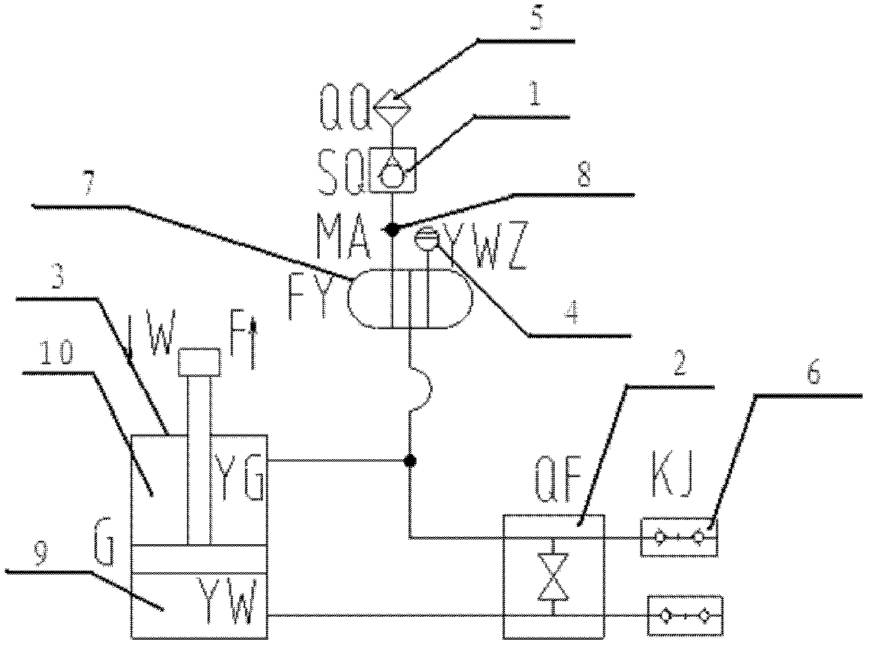
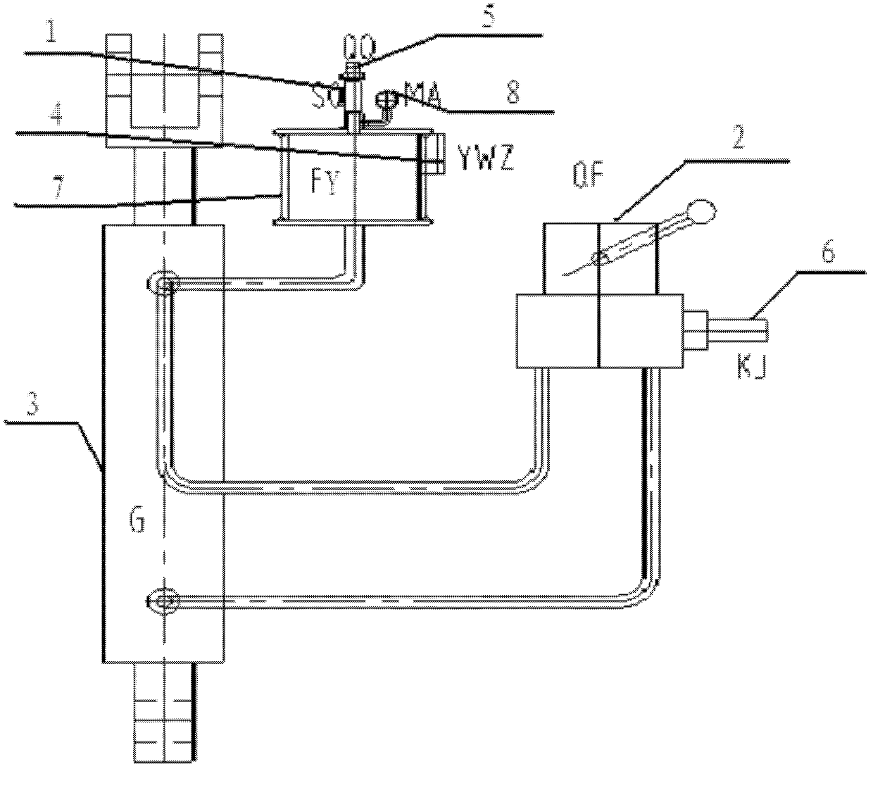
[0015] Under the action of external load, the hydraulic system uses the function of system pressurization to close and negative pressure to open to position the piston of the hydraulic cylinder and complete the hydraulic locking function.

[0016] Such as figure 1 , figure 2 As shown, including SQ one-way valve 1, QF manual stop valve 2, G hydraulic cylinder 3, YWZ liquid level gauge 4, QQ air filter 5, KJ quick-change joint 6, FY replenishment tank 7, MA pressure measuring point 8 , the two KJ quick-change joints 6 are connected to the QF manual shut-off valve 2 through pipelines, and the KJ quick-change joint 6 is the system oil injection port, and the system mu...


PUM


Abstract

The invention discloses a passive locking hydraulic system which comprises a SQ non-return valve, a QF manual globe valve, a G hydraulic cylinder, a YWZ liquid level meter, a QQ air cleaner, two KJ quick-change connectors, an FY oil filling tank, an MA pressure tap, wherein the two KJ quick-change connectors are connected with the QF manual globe valve, the QF manual globe valve is connected with the FY oil filling tank and the G hydraulic cylinder respectively, the QF manual globe valve, the FY oil filling tank and the G hydraulic cylinder are communicated with one another, the QF manual globe valve is connected with the G hydraulic cylinder through the equaling and equal volume pressure duct, the FY oil filling tank is sequentially connected with the MA pressure tap, the SQ non-return valve and the QQ air cleaner, the FY oil filling tank is provided with the YWZ liquid level meter, and the G hydraulic cylinder is provided with a YW oil cylinder rodless cavity and a YG oil cylinder rod cavity. The passive locking hydraulic system provided by the invention has the characteristics that the process is simple; closure is realized by use of system pressure boost and opening is realized by use of negative pressure; and hydraulic cylinder piston positioning is accurate.

Description

technical field [0001] The invention relates to the field of hydraulic equipment, in particular to a locking hydraulic device. Background technique [0002] Any hydraulic circuit is composed of some basic circuits. The basic circuit is composed of various components or accessories. The power source circuit is the most basic and indispensable part of the hydraulic system. It is generally composed of fuel tanks, fuel tank accessories, hydraulic pumps, electric motors, safety valves, filters, hydraulic valves, etc. The main parameters are pressure and flow. The locking hydraulic circuit generally has four types: reversing valve locking, one-way valve locking, hydraulic control one-way valve locking, and double hydraulic control one-way valve locking. However, in a place without electricity, the above locking circuits cannot be implemented. In order to meet the needs of operation in non-electric places, a passive locking hydraulic system is invented to realize accurate posi...

Claims


Application Information

Patent Timeline
Patent Type & Authority Patents(China)
IPC IPC(8): F15B15/26F15B21/00
Inventor 杨建国王瑛崔建英赵春江藏福占李国建李廷树王同会
Owner JULI SLING
Features
  • R&D
  • Intellectual Property
  • Life Sciences
  • Materials
  • Tech Scout
  • Unparalleled Data Quality
  • Higher Quality Content
  • 60% Fewer Hallucinations
Learn More