Lamp

A technology of lamps and annular parts, which is applied to lighting devices, cooling/heating devices of lighting devices, fixed lighting devices, etc. The effect of not easy to generate dust and easy to operate

Inactive Publication Date: 2013-07-24
AU OPTRONICS CORP
View PDF5 Cites 0 Cited by
  • Summary
  • Abstract
  • Description
  • Claims
  • Application Information

AI Technical Summary

Problems solved by technology

[0003] In the known technology, the light-emitting diode lamp tube 144 needs to use a large amount of aluminum heat dissipation material, and although the light box 142 and the aluminum heat dissipation material are not the main lighting equipment, they account for about 40% of the total cost of the lamp 140, resulting in the known clean room. Expensive for the used light fixture 140
In addition, in the known technology, the heat energy generated by the LED tube 144 will be accumulated in the light box 142, which will have a negative impact on the life of the LED tube 144 and the related driver.
In addition, when the lamp 140 needs to be repaired, the staff need to lift the iron plate 120 next to the lamp 140 to remove the lamp 140, which is not only difficult to replace, but also easily causes dust, which further pollutes the clean room
Furthermore, because the lamps 140 are arranged in the block 112, when designing the placement positions of the filter screen 130 and the lamp 140, the ideal positions of the filter screen 130 and the lamp 140 may overlap, resulting in some filter screens 130 or lamps 140 cannot be set in the ideal position

Method used


Image

  • Lamp
  • Lamp
  • Lamp

Examples


Embodiment Construction

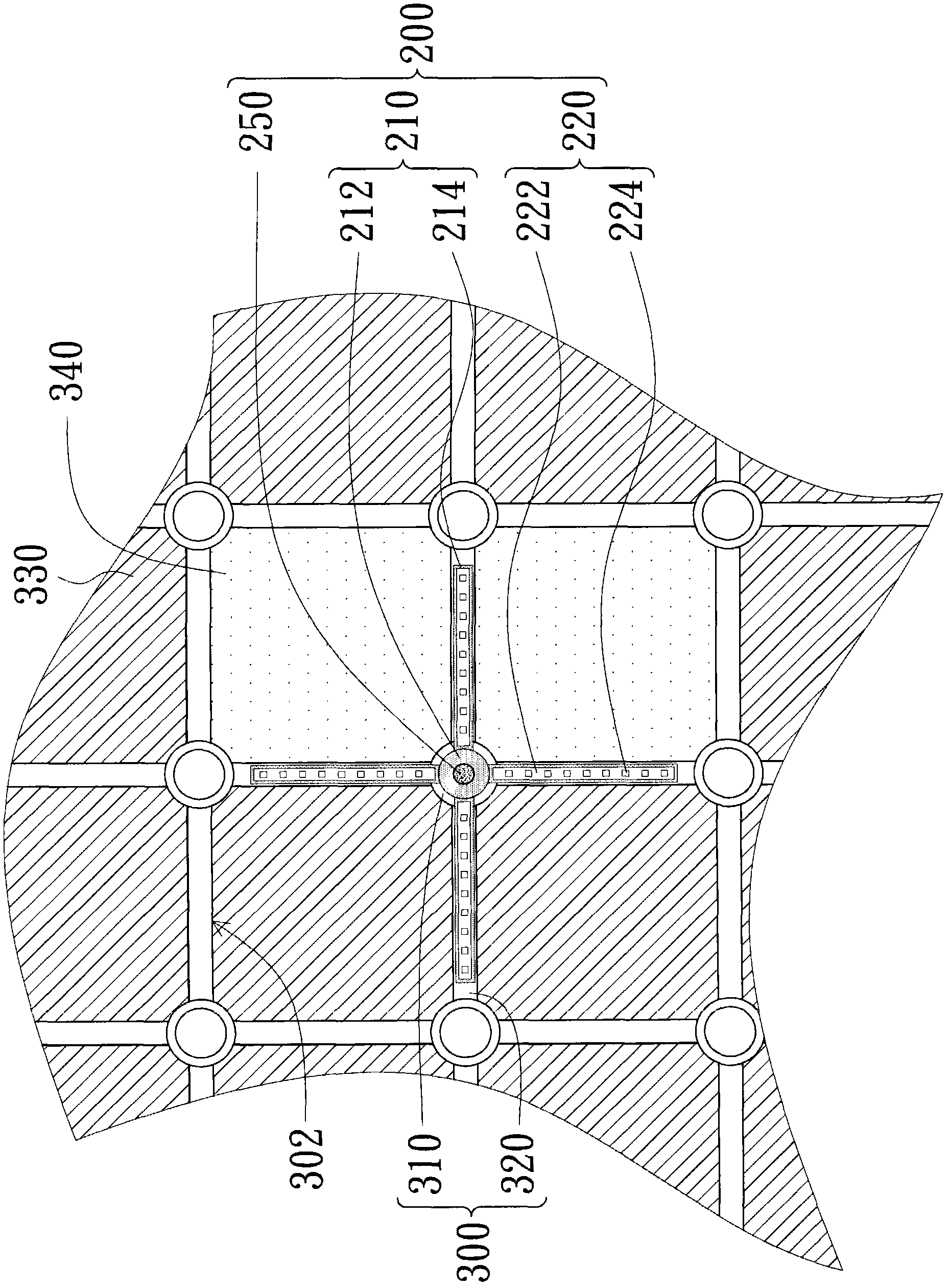
[0061] image 3 It is a schematic diagram of a lamp installed on a wall according to an embodiment of the present invention, and Figure 4 yes image 3 Schematic diagram of a cross-section of a light fixture. Please refer to image 3 and Figure 4 , the lamp 200 of this embodiment is suitable for being fixed on the wall 300 . The wall body 300 includes a plurality of coupling rings 310 and a plurality of supporting bars 320 . Each coupling ring 310 has an engaging hole 312 . The connecting ring 310 connects the supporting bars 320 to form a mesh frame. In this embodiment, the coupling ring 310 has a plurality of insertion holes 313 , and two ends of each support bar 320 are inserted into the corresponding insertion holes 313 of two adjacent coupling rings 310 . In addition, the wall body 300 can be a top wall of a clean room or other indoor spaces. The mesh frame is divided into a plurality of blocks 302 , and each block 302 can be covered with a cover 330 or have a fi...


PUM


Abstract

A lamp is suitable for being fixed on wall body. The wall body comprises a plurality of combination rings and a plurality of supporting strips. The combination rings are connected with the supporting strips for forming a net-shaped frame. The lamp comprises a base and at least one light emitting assembly. The base comprises at least annular part and at least one bearing part. Each annular part issuitable for being snapped in a snapping hole of a corresponding combination ring. Each bearing part is connected with the outer wall of at least one corresponding annular part and is adapted for contacting with a corresponding supporting strip. Each light emitting assembly is configured on a corresponding bearing part.

Description

technical field [0001] The present invention relates to a lamp, and in particular to a lamp suitable for use in a clean room. Background technique [0002] figure 1 is a schematic diagram of a known lamp installed on the top wall of a clean room, and figure 2 yes figure 1 Schematic diagram of the light fixture. Please refer to figure 1 and figure 2 , the top wall of the known clean room includes a mesh frame 110 composed of a plurality of steel bars, the mesh frame 110 is divided into a plurality of blocks 112 , and some blocks 112 are covered with iron plates 120 . In addition, for air circulation in the clean room, part of the block 112 needs to cover the filter screen 130 , and a fan unit must be installed above the filter screen 130 so that the air flow can pass through the filter screen 130 and flow into the clean room. In addition, it is known that the lamps 140 used in the clean room are also erected in the block 112 . The lamp 140 includes a light box 142 an...

Claims


Application Information

Patent Timeline
Patent Type & Authority Patents(China)
IPC IPC(8): F21S8/00F21V29/00F21V19/00F21V29/50
Inventor 黎隆庆
Owner AU OPTRONICS CORP
Why Eureka
Try Eureka