
Transmission method and equipment for downside control information

A technology for controlling information and transmission methods, which is applied in the field of communication and can solve problems such as lack of transmission and configuration schemes for E-PDCCH

Active Publication Date: 2012-03-28
DATANG MOBILE COMM EQUIP CO LTD
View PDF3 Cites 211 Cited by
  • Summary
  • Abstract
  • Description
  • Claims
  • Application Information

AI Technical Summary

Problems solved by technology

[0018] Embodiments of the present invention provide a downlink control information transmission method and equipment, which solves the problem of lack of specific transmission and configuration schemes for E-PDCCH in localized and distributed transmission modes in existing technical solutions

Method used


Image

  • Transmission method and equipment for downside control information
  • Transmission method and equipment for downside control information
  • Transmission method and equipment for downside control information

Examples


Embodiment 1

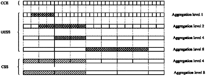
[0157] For localized E-PDCCH resources, the number of candidate E_PDCCH channels with aggregation levels {1, 2, 4, 8} in each E-PDCCH cluster is {2, 2, 2, 1}, if localized E-PDCCH The number of E-PDCCH clusters contained in the resource is 2, then the total number of blind detection times is calculated as follows:

[0158] The number of blind detections required in each E-PDCCH cluster is (2+2+2+1)*2=14, where the last 2 indicates that two DCI formats need to be blindly detected in one E-PDCCH candidate channel.

[0159] The number of E-PDCCH clusters is 2.

[0160] The total number of times of blind detection is 14*2=28.

Embodiment 2

[0162] For distributed E-PDCCH resources, the number of candidate E_PDCCH channels with aggregation levels {1, 2, 4, 8} is {6, 6, 2, 2}, then the total number of blind detection times is (6+6+ 2+2)*2=32, where the last 2 indicates that two DCI formats need to be blindly detected in one E-PDCCH candidate channel.

[0163] For method 2, the search space of the localized E-PDCCH resource and the search space of the distributed E-PDCCH resource share the maximum number of blind detection times of the PDCCH, which requires a reasonable allocation of the respective search spaces of the localized E-PDCCH resource and the distributed E-PDCCH resource The number of PDCCH blind detection times in .

Embodiment 3

[0165] Two E-PDCCH clusters are configured in the localized E-PDCCH resource, and the number of candidate E_PDCCH channels with aggregation levels {1, 2, 4, 8} in each E-PDCCH cluster is {2, 2, 0, 0} , in the distributed E-PDCCH resources, the number of candidate E_PDCCH channels with aggregation levels {1, 2, 4, 8} is {2, 2, 2, 2}. Then the calculation process of the total number of blind detection times is as follows.

[0166] Blind detection times in Localized E-PDCCH resources:

[0167] The number of blind detections required in each E-PDCCH cluster is (2+2+0+0)*2=8, where the last 2 indicates that two DCI formats need to be blindly detected in one E-PDCCH candidate channel.

[0168] The number of E-PDCCH clusters is 2.

[0169] Therefore, the number of times of blind detection in the Localized E-PDCCH resource is 8*2=16.

[0170] Number of blind detections in Distributed E-PDCCH resources:

[0171] It is (2+2+2+2)*2=16, where the last 2 indicates that two DCI formats ...


PUM


Abstract

The embodiment of the invention discloses transmission method and equipment for downside control information. By adopting the technical scheme of the embodiment of the invention, the transmission method is capable of supporting two transmission modes of an E-PDCCH (physical downside control information channel) effectively, allocating a localized E-PDCCH resource and a distributed E-PDCCH resource by a base station, detecting DCI formats in search spaces corresponding to the localized E-PDCCH resource and the distributed E-PDCCH resource by terminal equipment, and obtaining the downside control information transmitted by the base station, thereby solving the problem in the existing technical scheme that the specific transmission and allocation schemes for the E-PDCCH in a localized transmission mode and a distributed transmission mode are lacked, so that the E-PDCCH can obtain channel selection gains and diversity transmission gains.

Description

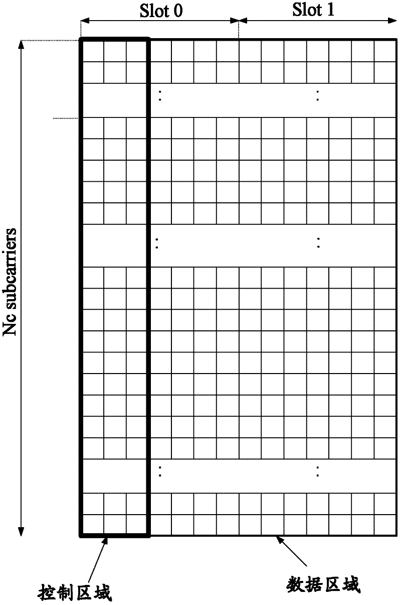
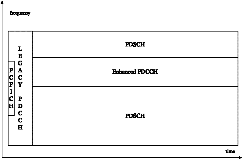
technical field [0001] The present invention relates to the field of communication technology, in particular to a method and equipment for transmitting downlink control information. Background technique [0002] In the LTE (Long Term Evolution, long-term evolution) system, PDCCH (Physical Downlink Control Channel, Physical Downlink Control Channel) is sent in each radio subframe, and shared with downlink data PDSCH (Physical Downlink Shared Channel, Physical Downlink Channel) ) form a TDM (Time Division Multiplexed, time division multiplexing) multiplexing relationship. PDCCH is transmitted through the first N OFDM (Orthogonal Frequency Division Multiplexing) symbols of a downlink subframe, where N may be 1, 2, 3, 4, and N=4 is only allowed to appear in In a system with a system bandwidth of 1.4MHz. [0003] like figure 1 As shown, it is a schematic diagram of the multiplexing relationship between the control region and the data region in a downlink subframe in the prior ...

Claims


Application Information

Patent Timeline
Patent Type & Authority Applications(China)
IPC IPC(8): H04W72/04H04W72/12
CPCH04L5/0032H04L1/0038H04W72/12H04L5/0041H04W72/042H04W72/04H04L5/0053H04W72/23
Inventor 赵锐潘学明沈祖康张然然
Owner DATANG MOBILE COMM EQUIP CO LTD
Learn More