Steam sterilization apparatus

A disinfection device, steam technology, applied in the direction of injection device, injection device, liquid injection device, etc., can solve the problems of pump 102 damage, decrease in steam generation efficiency, large volume, etc., and achieve easy replacement or cleaning, easy to carry and move, The effect of size reduction

Inactive Publication Date: 2012-03-28
ECO INNTOT
View PDF4 Cites 2 Cited by
  • Summary
  • Abstract
  • Description
  • Claims
  • Application Information

AI Technical Summary

Problems solved by technology

[0008] First, the boiler 201 is not heated during the initial stage of operation of the steam sterilizer, nor is the water flowing into the boiler 201 heated, so that the water flowing into the boiler 201 is discharged in liquid phase through the steam injection nozzle 301, with the result that there is The problem: not being able to achieve the disinfection effect by steam at the initial stage of operation
[0009] Second, when using a steam sterilizer, the heat generated from the boiler 201 is quickly delivered to the pump through the second water supply pipe 200 formed of a metal material, so that the pump 102 is easily damaged due to heat transfer, and when the pump is operated At 102, a wave phenomenon occurs in the moving water, causing the steam to spray erratically
[0010] Third, the space provided in the boiler 201 for heating the water flowing in from the water container, that is, the vaporization passage, is formed of a heating wire rod, so that the generation efficiency of steam is reduced, and the boiler 201 with this structure has a large volume, causing the steam The overall volume of the sterilizer increases, which reduces the mobility of the steam sterilizer

Method used


Image

  • Steam sterilization apparatus
  • Steam sterilization apparatus
  • Steam sterilization apparatus

Examples


Embodiment Construction

[0034] Hereinafter, exemplary embodiments of the present invention will be described below with reference to the accompanying drawings.

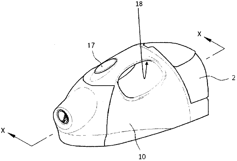
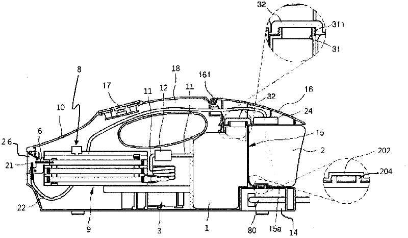
[0035] figure 2 is a perspective view of the external structure of the steam sterilizer according to the first example embodiment of the present invention, and image 3 is shown along figure 2 Cross-sectional view of the internal structure of the steam sterilizer taken along the line x-x shown.

[0036] refer to figure 2 with image 3 , the steam sterilizer according to the first exemplary embodiment of the present invention includes: a housing 10 forming a main body; a water container 1 disposed at the inner rear of the housing 10 to store water; a chemical liquid container 2 disposed at After the water container 1 to store the chemical liquid; the nozzle assembly 26 is arranged at the inner front of the housing 10 and includes the steam nozzle 6 and the chemical liquid nozzle 21, wherein the steam nozzle 6 is used to receive the wat...


PUM


Abstract

The present invention relates to a steam sterilization apparatus, and more particularly, to a steam sterilization apparatus in which a crack in a vaporization space is minimized to achieve maximized water vaporization efficiency and to reduce the size of the apparatus, and which prevents liquid phase water from being sprayed at an early stage of operation of the apparatus to achieve a steam sterilization effect from the early stage of operation of the apparatus. The steam sterilization apparatus according to the present invention comprises: a case which forms a main body; a water container arranged in an inner rear portion of the case to store water; a liquid chemical container arranged behind the water container to store a liquid chemical; a nozzle assembly which is arranged in an inner front portion of the case and which includes a steam nozzle for receiving water from the water container and spraying water to the outside, and a liquid chemical nozzle for receiving a liquid chemical from the liquid chemical container and discharging the liquid chemical to the outside; a water supply pipe which interconnects the water container and the steam nozzle; a liquid chemical supply pipe which interconnects the liquid chemical container and the liquid chemical nozzle; a heater block interposed between the water supply pipe and the steam nozzle to heat and vaporize the water supplied through the water supply pipe; a pump installed at the water supply pipe to apply pressure to the water in the water container and to supply water through the water supply pipe; and a control unit which controls the operation of the pump and of the heater block.

Description

technical field [0001] The present invention relates to a steam sterilizing device, and more particularly, to a steam sterilizing device in which the gaps in the vaporization space are minimized to maximize water vaporization efficiency and reduce the size of the device. size, and the steam sterilizing device prevents spraying of liquid-phase water at the initial stage of operation of the device to achieve the steam sterilizing effect from the initial stage of operation of the device. Background technique [0002] In general, a steam sterilizer means a device that achieves a sterilizing effect by mixing a chemical liquid with sprayed steam, and a typical steam sterilizer known in the related art will be described below. [0003] figure 1 is an overall configuration diagram showing an "injection device" of Korean Patent Registration No. 712639 (hereinafter, referred to as a "steam sterilizer in the related art"). [0004] refer to figure 1 , the steam sterilizer in the rel...

Claims


Application Information

Patent Timeline
Patent Type & Authority Applications(China)
IPC IPC(8): A61L2/07A61L2/18B05B7/08B05B9/04B05B12/10B05B1/24B05B1/30
CPCA61L2/07A61L2/18B05B7/2429
Inventor 李种彻
Owner ECO INNTOT
Why Eureka
Try Eureka