
Automatic calibration method for sensor of breathing machine

An automatic calibration, ventilator technology, applied in the direction of respirator, machine/engine, test/calibration device, etc., can solve the problem of tedious calibration steps of ventilator, and achieve the effect of speeding up progress and improving production efficiency

Active Publication Date: 2012-04-04
航天长峰医疗科技(成都)有限公司
View PDF4 Cites 28 Cited by
  • Summary
  • Abstract
  • Description
  • Claims
  • Application Information

AI Technical Summary

Problems solved by technology

[0004] The purpose of the present invention is to solve the cumbersome calibration steps of the existing ventilator, provide a fully automatic ventilator sensor calibration method, simplify the calibration process, and improve the accuracy and reliability of the calibration results

Method used


Image

  • Automatic calibration method for sensor of breathing machine
  • Automatic calibration method for sensor of breathing machine

Examples


Embodiment Construction

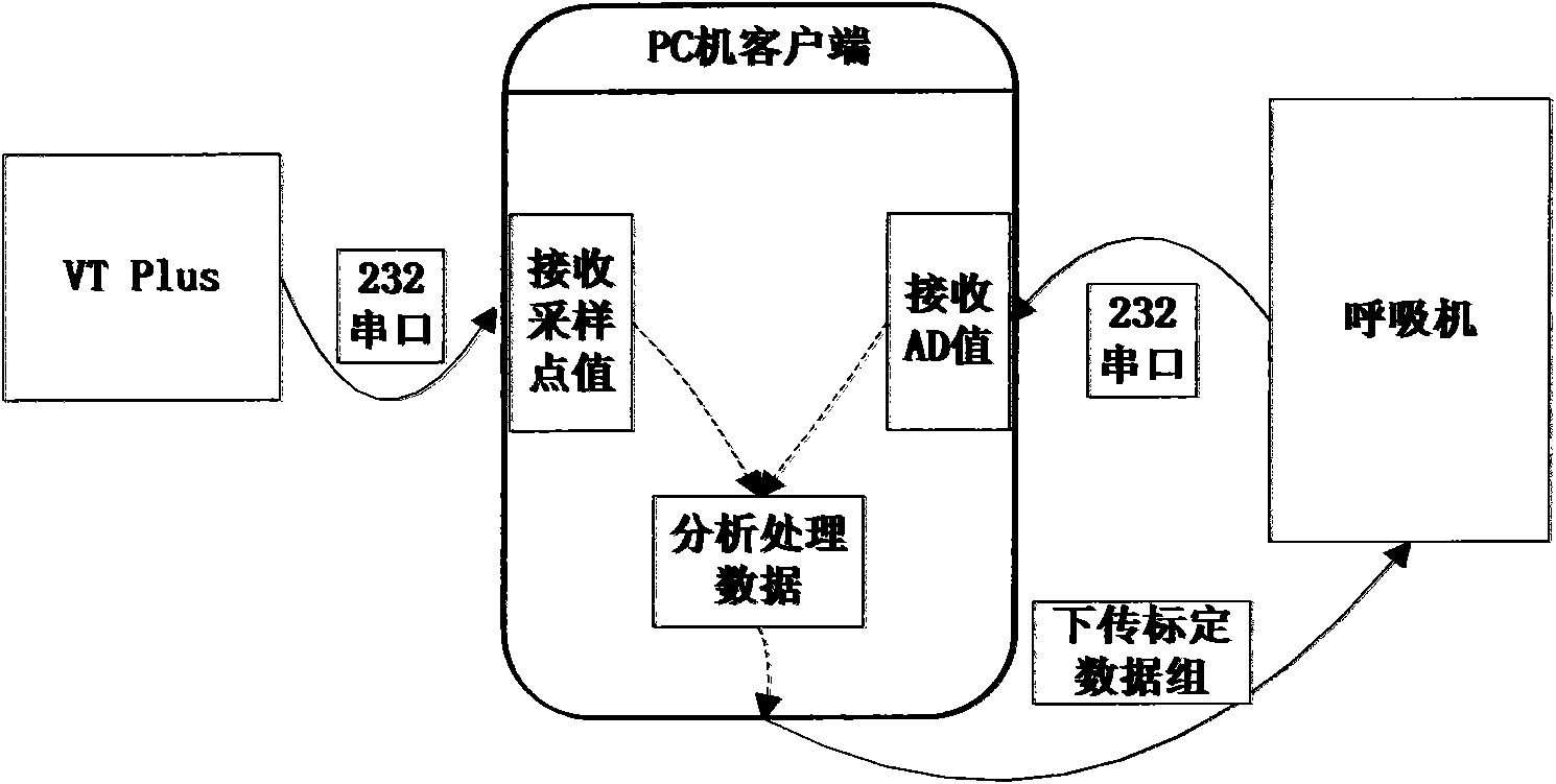
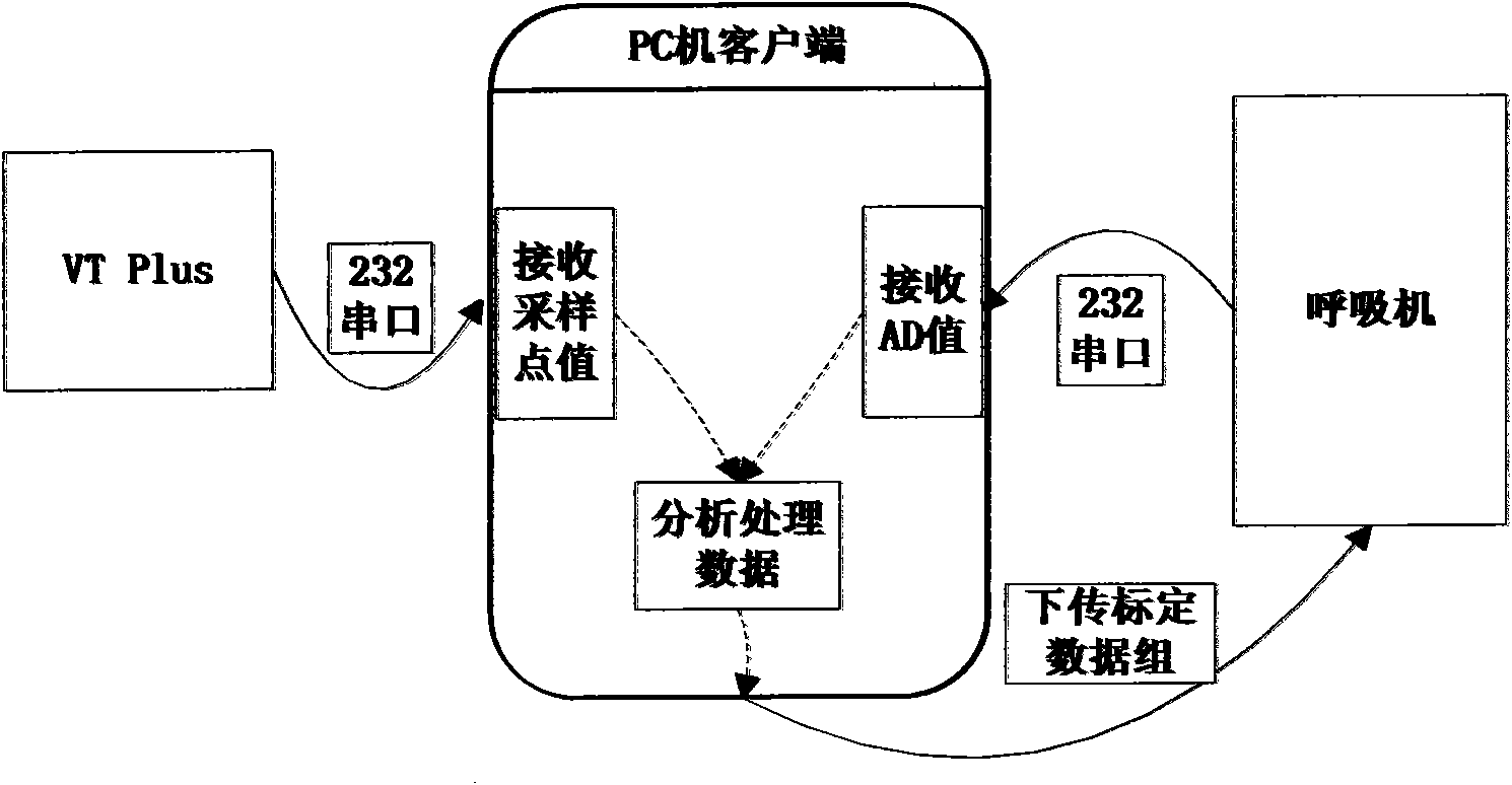
[0018] Such as figure 1 As shown, the equipment that the present invention needs to use includes computer, ventilator equipment to be calibrated and calibration air circuit, and airflow analyzer, wherein the computer can adopt common PC machine, and airflow analyzer can adopt the VT Plus airflow analysis of American Fluke Company instrument. Connect the airflow analyzer to the gas circuit of the ventilator, connect the airflow analyzer to the PC through the RS232 communication interface, and connect the ventilator to the PC through the RS232 communication interface.

[0019] The invention can realize the automatic calibration of the ventilator sensor, including the calibration of the pressure sensor and the flow sensor, as well as the calibration of the blower fan and the breathing valve.

[0020] When calibrating, set multiple data sampling points, and at each data sampling point, send a calibration command to the ventilator through the computer, and the gas flow analyzer an...


PUM


Abstract

The invention discloses an automatic calibration method for a sensor of a breathing machine. The method comprises the following steps that: a gas flow analyzer is connected with a breathing machine gas channel and communicates with a personal computer (PC), the breathing machine communicates with the PC, a plurality of data sampling spots are set, a calibration command is transmitted at each data sampling spot by the computer, the gas flow analyzer and the breathing machine receive the calibration commands and automatically reply with monitored parameter values, received sampling spot data and a breathing machine average deviation (AD) value are analyzed by the computer, a calibration curve is automatically drawn, and a final calibration result is transmitted to the breathing machine.

Description

technical field [0001] The invention relates to an automatic calibration method for a ventilator sensor, in particular to the automatic calibration of a pressure sensor, a flow sensor, a breathing valve and a fan of the ventilator, and belongs to the technical field of medical equipment manufacturing. Background technique [0002] The ventilator has very important clinical value for respiratory failure and clinical rescue treatment. Its working principle is that the air is filtered and mixed with low-pressure oxygen, and then compressed by the turbo fan to form a gas with a certain pressure and enter the breathing valve along the airway, and the controlled gas flows out of the inhalation port, and finally reaches the patient's end, providing the patient with a mechanical ventilation. The gas flow rate is monitored by a flow sensor on the controlled gas path, and the patient-side pressure is monitored by a pressure sensor at the patient inlet. Pressure and flow rate signals...

Claims


Application Information

Patent Timeline
IPC IPC(8): A61M16/20G01L27/00G01F25/00F04B51/00
Inventor 魏瑞丽
Owner 航天长峰医疗科技(成都)有限公司
Features
  • Generate Ideas
  • Intellectual Property
  • Life Sciences
  • Materials
  • Tech Scout
  • Unparalleled Data Quality
  • Higher Quality Content
  • 60% Fewer Hallucinations
Learn More