Centrifugal pump with cutting devices

A technology with cutting, centrifugal pumps, applied in the direction of components, pumps, pump elements, etc. of pumping devices for elastic fluids

Inactive Publication Date: 2012-04-04
JIANGSU GUOQUAN PUMP MFG CO LTD
View PDF4 Cites 5 Cited by
  • Summary
  • Abstract
  • Description
  • Claims
  • Application Information

AI Technical Summary

Problems solved by technology

[0003] The technical problem to be solved by the present invention is how to design the structure of the front section of the centrifugal pump to crush debris, improve the anti-clogging ability of the pump, and improve the performance of the pump

Method used


Image

  • Centrifugal pump with cutting devices
  • Centrifugal pump with cutting devices
  • Centrifugal pump with cutting devices

Examples


Embodiment Construction

[0009] In order to make the technical means, innovative features, objectives and effects achieved by the present invention easy to understand, the present invention will be further described below in conjunction with the accompanying drawings.

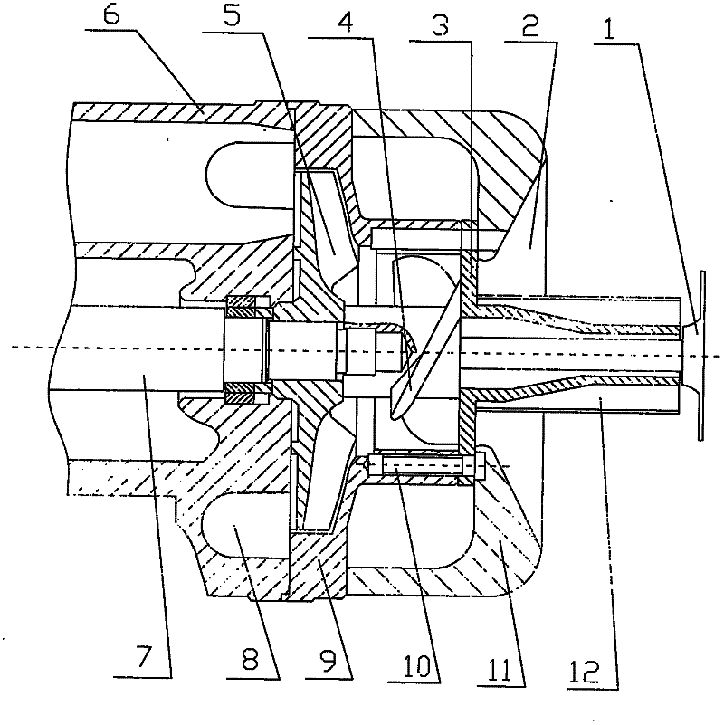
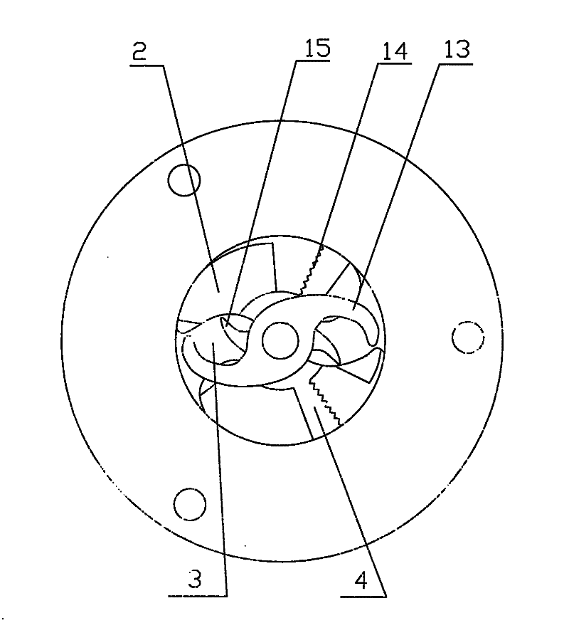
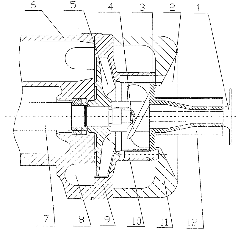
[0010] The centrifugal pump of the present invention adopts a triple cutting structure. This structure is used to crush the sundries in the sewage, improve the degree of non-blocking, and then improve the performance of the centrifugal pump. The cutting knife at the front end, the cutting impeller and the main impeller all rotate with the pump shaft. The cutting knife adopts two S-shaped shapes, and the cutting edge on the cutting impeller adopts three saw-toothed shapes.

[0011] Structure description

[0012] Such as figure 1 As shown, the centrifugal pump consists of a cutter (1), an inlet (2), a fixed cutter (3), a cutter impeller (4), a main impeller (5), a pump casing (6), a pump shaft (7), an outlet (8 ), main impeller front...


PUM


Abstract

The invention relates to a centrifugal pump with cutting devices. Triple cutting devices are arranged at the front section of the centrifugal pump. Firstly, the ingress of an S-shaped cutter is arranged, then a conical cutting edge with a sharp cutting tool is arranged, and finally a cutting impeller and a corresponding fixed cutting tool are arranged. The cutting edge on the cutting impeller adopts a sawtooth shape; all the cutting impeller, the S-shaped cutter and a main impeller rotate along with a pump shaft; and the fixed cutting tool and the conical cutting edge are fixed at the front end of the cutting impeller.

Description

technical field [0001] The invention relates to a centrifugal pump with a cutting device. Background technique [0002] In sewage treatment, there are often some large debris such as rags and plastics. These debris tend to wrap around the impeller and cause a blockage in the pump, preventing the pump from running. Therefore, necessary components are added to the front section of the impeller to crush these sundries. Contents of the invention [0003] The technical problem to be solved by the present invention is how to design the structure of the front section of the centrifugal pump to crush debris, improve the anti-clogging ability of the pump, and improve the performance of the pump. [0004] In order to solve the above problems, the technical solution adopted in the present invention is: [0005] A triple cutting device is installed in the front section of the impeller of the centrifugal pump. First the cutting knife at the inlet, then the conical cutting edge with...

Claims


Application Information

Patent Timeline
Patent Type & Authority Applications(China)
IPC IPC(8): F04D1/00F04D29/00
Inventor 朱荣生杨爱玲
Owner JIANGSU GUOQUAN PUMP MFG CO LTD
Why Eureka
Try Eureka