Thread cutting insert for thread turning processing and external thread component manufacturing method

A technology for cutting inserts and cutting threads, applied in thread cutting tools, manufacturing tools, metal processing equipment, etc., can solve the problems of insufficient size and damage to the precision of the machined surface, and achieve the improvement of cutting edge strength and cutting edge strength. Effect

Inactive Publication Date: 2018-05-01
NGK SPARK PLUG CO LTD
View PDF6 Cites 2 Cited by
  • Summary
  • Abstract
  • Description
  • Claims
  • Application Information

AI Technical Summary

Problems solved by technology

The reason for this is that in the thread machining realized by turning, continuous cutting is performed in the transverse feed, and the rake face (the face that forms the cutting edge together with the flank face) 23 that forms the cutting edge 21 during the entire stroke The periphery is in contact with the forming surface (machined surface) of the thread groove, and even if the sub relief surface 26m has a relief angle, if the main relief surface 26a does not have a relief angle (main relief angle α), or even if the main relief surface In the case where the flank 26a has a main relief angle α but its magnitude is not sufficient, it is also due to the lead angle, but particularly because the main flank 26a on the advancing side of the cutting edge 21 contacts or interferes with the machined surface , so damage the machining surface accuracy (finishing surface roughness)

Method used


Image

  • Thread cutting insert for thread turning processing and external thread component manufacturing method
  • Thread cutting insert for thread turning processing and external thread component manufacturing method
  • Thread cutting insert for thread turning processing and external thread component manufacturing method

Examples


Embodiment Construction

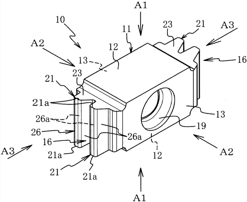
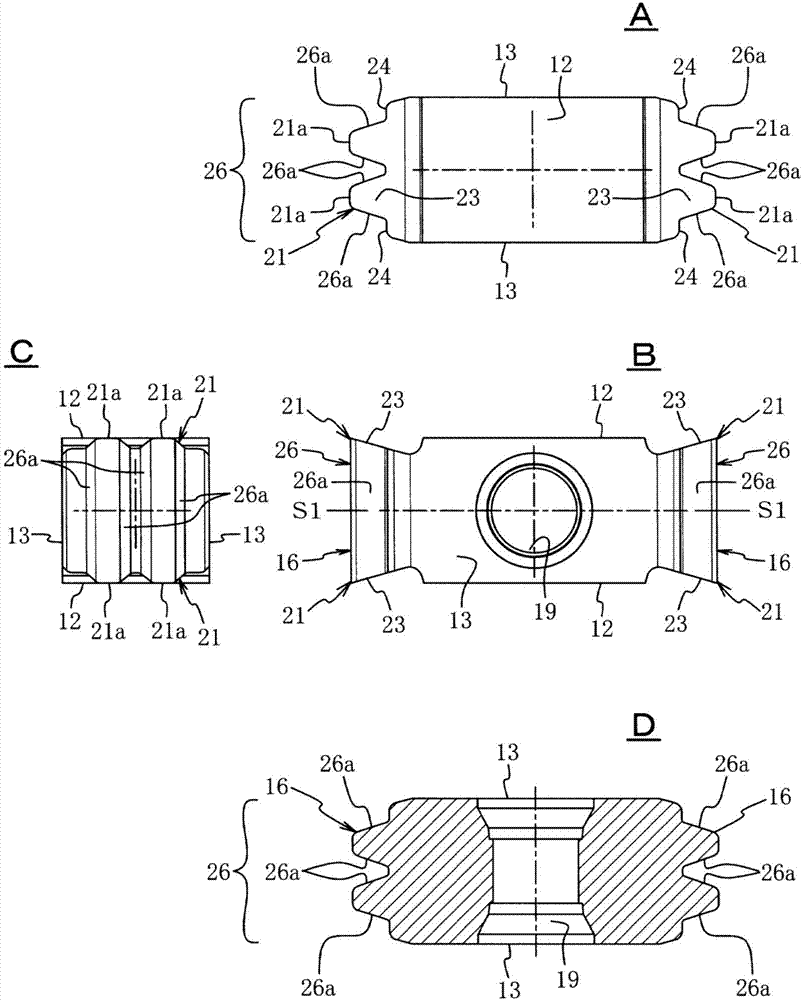
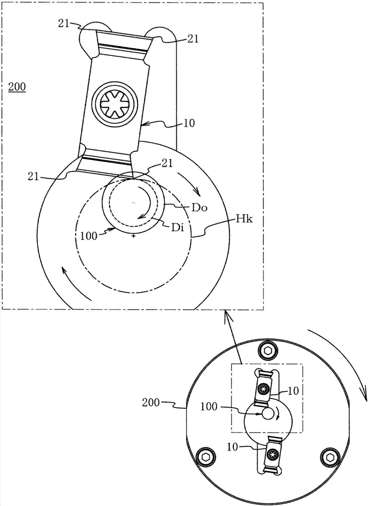
[0044] refer to Figure 1 to Figure 5 An embodiment example in which the cutting insert for thread cutting in thread turning machining according to the present invention is embodied will be described. Among them, such as Figure 5 As shown, for the cutting insert (non-regrinding cutting insert) 10 of this example, the thread (thread thread) to be formed is a triangular thread with a slightly flat top (top) (the angle of the thread thread is 40 degrees) , the threaded thread 105 is left-right symmetrical on a section passing through the axis Gn of the shaft member 100 (left-right symmetrical with respect to the central axis Yc in the width direction of the threaded thread 105), and the cutting insert 10 is used to process a thread by one feed The groove is trapezoidal and the width in the lead direction is larger than the two threads of the thread teeth. Therefore, if figure 1 , figure 2 As shown, the shape (cutting edge shape) of the cutting insert 10 when viewing the cu...


PUM


Abstract

The present invention relates to a thread cutting insert for thread turning processing, and the cutting insert has a thread cutting edge formed on the outer peripheral surface of a shaft member by thread turning processing. A thread groove is bilaterally symmetrical in the section passing through the axis of the shaft member, and thus does not cause the reduction of machining surface accuracy, soas to reduce the cost of processing. The cutting edge is formed in a manner that the one side face of the cutting insert is used as the flank face, and the common flank face with the main flank angleof 0 is formed as the flank face, and the rake face is formed on the front and rear surfaces of the cutting insert. There are two cutting edges on one side of the face. In the thread turning process,interrupted cutting of minute portions is performed, and the cutting edge after one cutting operation is a machining surface away from the thread groove processed by the previous cutting. Therefore, without the main relief angle, the machining surface accuracy is not reduced. Therefore, the cutting insert is provided with the cutting edge on the front and back without the main relief angle, and the cutting edge strength is improved without reducing the accuracy of the machining surface, thereby reducing the cost of the machining.

Description

technical field [0001] The present invention relates to a cutting insert for thread cutting in thread turning machining (hereinafter also referred to as a cutting insert for thread cutting, or simply referred to as a cutting insert), and a thread turning machining method using the cutting insert. Method for externally threaded members. Background technique [0002] There are various processing methods for forming external threads (hereinafter also referred to as "threads") on the outer peripheral surface of a shaft member (round bar), and the thread turning method is one of them (Patent Document 1). This processing method is as follows: While rotating a shaft member (raw material) as a processing object (workpiece) at a low speed (for example, 5rpm to 10rpm), it feeds the thread to be formed along the axial direction during one revolution (1 thread ), on the other hand, make the cutting edge (tip) of one or more cutting inserts (or tools) in a circle that is larger than the...

Claims


Application Information

Patent Timeline
Patent Type & Authority Applications(China)
IPC IPC(8): B23G5/00B23G1/00
CPCB23G1/00B23G5/00
Inventor 矶部健二
Owner NGK SPARK PLUG CO LTD
Why Eureka
Try Eureka