

Method for manufacturing floating gate discharging sharp corner
A manufacturing method and floating gate technology, applied in the manufacture of circuits, electrical components, semiconductors/solid-state devices, etc., can solve problems such as poor stability and flash memory erasing speed limitations
- Summary
- Abstract
- Description
- Claims
- Application Information
AI Technical Summary
Problems solved by technology
Method used
Image

Examples
Embodiment
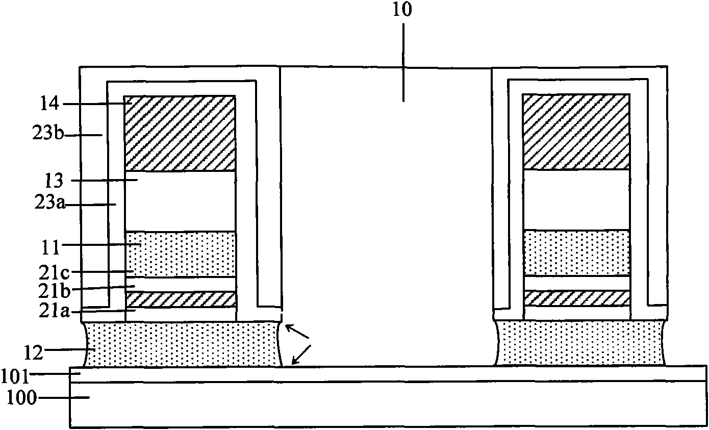
[0030] Refer below Figure 2 to Figure 7 The specific content of this embodiment will be described in detail. The manufacturing steps of the floating gate discharge peak of the present embodiment include:
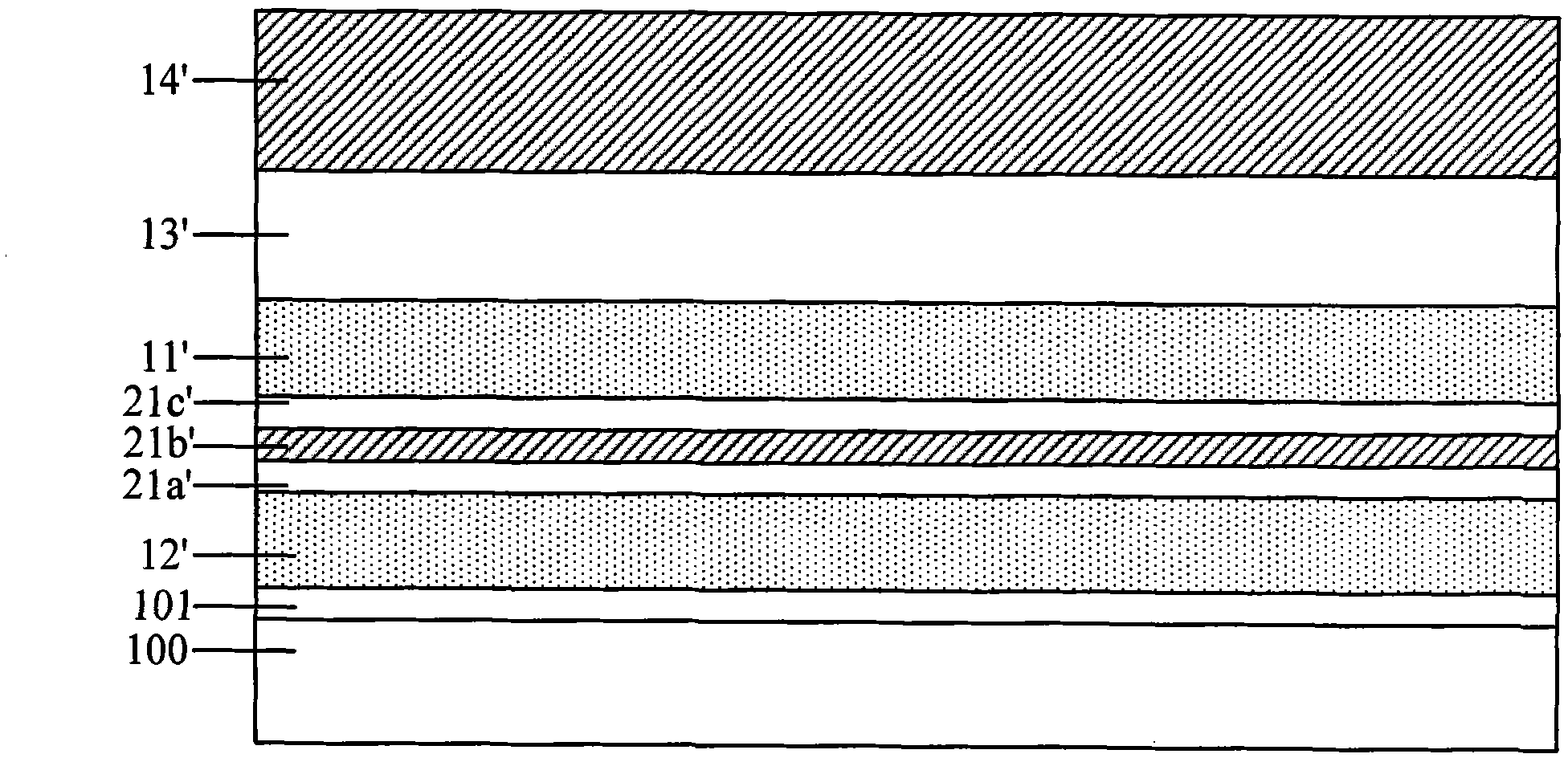
[0031] Step 1: See figure 2 As shown, a first oxide layer 101, a floating gate layer 12', a first silicon oxynitride layer 21a', a second oxide layer 21b', a second silicon oxynitride layer 21c', and a control gate layer are sequentially formed on a substrate 100. 11', the third oxide layer 13', and the third silicon oxynitride layer 14'; wherein, the materials of the first oxide layer 101, the second oxide layer 21b', and the third oxide layer 13' can be but not limited to silicon oxide.
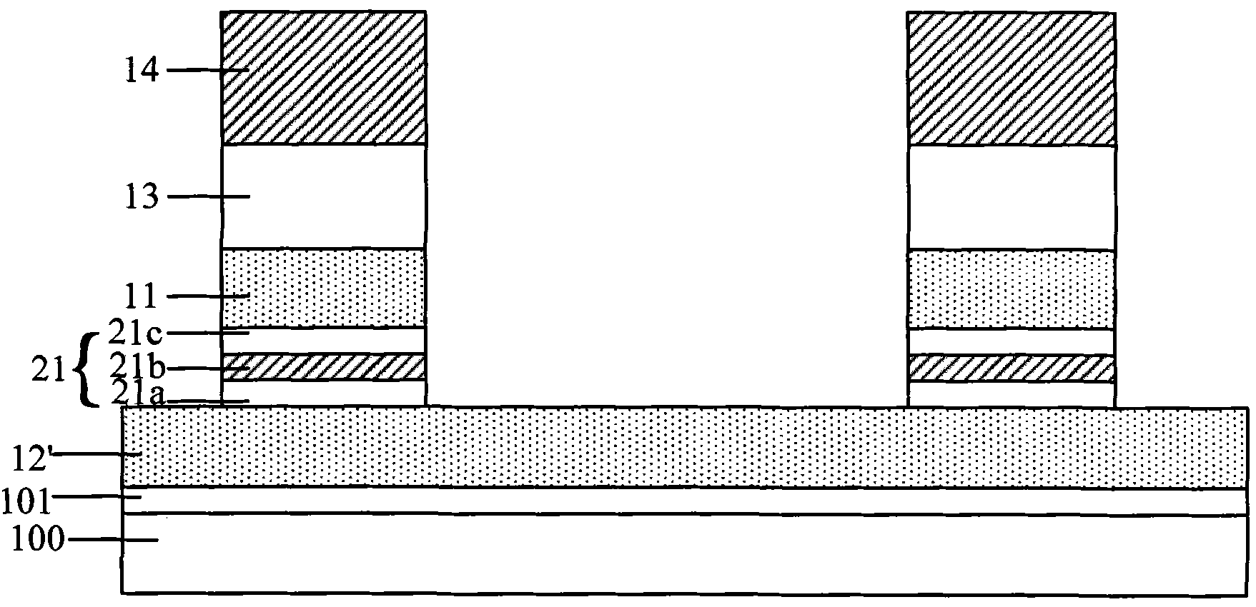
[0032] Step 2: see image 3 As shown, for the first silicon oxynitride layer 21a', the second oxide layer 21b', the second silicon oxynitride layer 21c', the control gate layer 11', the third oxide layer 13', the third silicon oxynitride layer 14' for masking and etching to form th...
PUM
| Property | Measurement | Unit |
|---|---|---|
| Thickness | aaaaa | aaaaa |
Abstract
Description
Claims
Application Information