Hydraulic valve, hydraulic system and concrete pumping equipment

A hydraulic system and hydraulic valve technology, which is applied in the fields of hydraulic systems, hydraulic valves, and concrete pumping equipment, can solve problems such as pipe blockage and inability to perform emergency pumping, and achieve the effect of avoiding pipe blockage and increasing displacement

Inactive Publication Date: 2012-04-04
SANY AUTOMOBILE MFG CO LTD
View PDF4 Cites 9 Cited by
  • Summary
  • Abstract
  • Description
  • Claims
  • Application Information

AI Technical Summary

Problems solved by technology

In the above scheme, the pumping hydraulic system can only be used as an emergency oil supply for the boom hydraulic system. When the main oil pump of the pumping hydraulic system fails, emergency pumping cannot be performed, which will lead to pipe blockage

Method used


Image

  • Hydraulic valve, hydraulic system and concrete pumping equipment
  • Hydraulic valve, hydraulic system and concrete pumping equipment
  • Hydraulic valve, hydraulic system and concrete pumping equipment

Examples


Embodiment Construction

[0023] In order to enable those skilled in the art to better understand the technical solution of the present invention, the present invention will be further described in detail below in conjunction with the accompanying drawings and specific embodiments. It should be pointed out that the description and sequence of specific structures in this section are only descriptions of specific embodiments, and should not be considered as limiting the protection scope of the present invention.

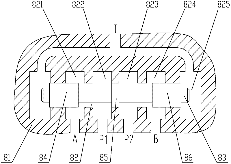
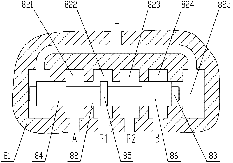
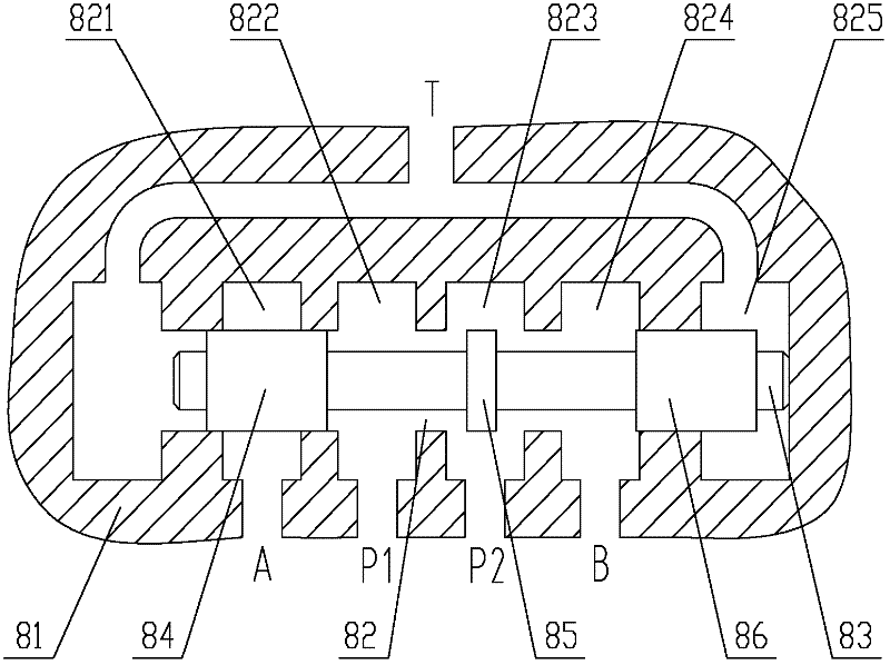
[0024] Please refer to Figure 1 to Figure 4 ,in, figure 1 It is a schematic structural diagram of a hydraulic valve in the first working state provided by the embodiment of the present invention, figure 2 for figure 1 The structural schematic diagram of the hydraulic valve shown in the second working state, image 3 for figure 1 and 2 The structural schematic diagram of the hydraulic valve shown in the third working state, Figure 4 for Figure 1 to Figure 3 The hydraulic graphic symbo...


PUM


Abstract

The invention relates to the technical field of engineering machinery and discloses a hydraulic valve, a hydraulic system and concrete pumping equipment, wherein the hydraulic valve comprises a valve body, a valve rod and a driving part, wherein the valve body is provided with a valve cavity; the valve rod is arranged in the valve cavity; the driving part drives the valve rod to move in the valve cavity; the valve cavity is provided with a first oil inlet, a second oil inlet, a first oil outlet and a second oil outlet; under a first working state, the first oil inlet is communicated with the first oil outlet; the second oil inlet is communicated with the second oil outlet; under a second working state, the first oil inlet and the second oil inlet are respectively communicated with the first oil outlet, and the second oil outlet is closed; and under a third working state, the first oil inlet and the second oil inlet are respectively communicated with the second oil outlet, and the first oil outlet is closed. The embodiment of the invention provides the hydraulic system applying the hydraulic valve, so that the function of mutual oil filling or emergent oil supplying are achieved between the hydraulic system for pumping and a hydraulic system of an arm frame, and the occurrence of the phenomenon that the progress of the engineering is influenced or pipes are blocked is effectively avoided.

Description

technical field [0001] The invention relates to the technical field of engineering machinery, in particular to a hydraulic valve and a hydraulic system provided with the hydraulic valve. The invention also relates to a concrete pumping plant provided with the hydraulic system described above. Background technique [0002] With the rapid development of economic construction, the market demand for construction machinery, especially concrete pump trucks, is increasing. Concrete pumping equipment generally includes a walking device, a pumping device and a boom device. The walking device is mainly used for the transfer of the working place of the pumping equipment, and the pumping device and the boom device are used to transport concrete to the place where concrete is needed during the construction process. . [0003] The pumping hydraulic system of the concrete pump truck and the boom hydraulic system are two independent systems. The hydraulic oil of the pumping system is prov...

Claims


Application Information

Patent Timeline
Patent Type & Authority Applications(China)
IPC IPC(8): F15B13/02F15B11/17
Inventor 王术冬刘江明黄勃
Owner SANY AUTOMOBILE MFG CO LTD
Why Eureka
Try Eureka