Eureka AIR delivers breakthrough ideas for toughest innovation challenges, trusted by R&D personnel around the world.

Cutting machine with movable backup plate

A mobile, cutting machine technology, applied in the direction of manufacturing tools, metal sawing equipment, sawing machine devices, etc., can solve problems such as increased damage rate of parts and adjustment of unfavorable micro-dimensions

Inactive Publication Date: 2012-04-11
REXON IND CORP LTD
View PDF7 Cites 2 Cited by
  • Summary
  • Abstract
  • Description
  • Claims
  • Application Information

AI Technical Summary

Problems solved by technology

[0003] When cutting workpieces of different widths, the distance between the saw blade and the backing board must also be different. Therefore, the backing board is designed as a movable backing board, allowing users to adjust the position of the backing board according to workpieces of different widths and sizes , but the previous patent did not reveal the fine-tuning backing plate, which is not conducive to the adjustment of micro-sized
[0004] In the US2009 / 0277315A1 patent, a movable backing board is used to fix the backing board after the position of the backing board is adjusted, but this kind of fixing method will not As a result, when the user wants to adjust the position of the leaning plate again, it is easy to forget to loosen the leaning plate and the workbench surface. The result of direct application of force without loosening will increase the damage rate of parts

Method used


Image

  • Cutting machine with movable backup plate
  • Cutting machine with movable backup plate
  • Cutting machine with movable backup plate

Examples


Embodiment Construction

[0025] Below in conjunction with accompanying drawing and embodiment the present invention is described in detail:

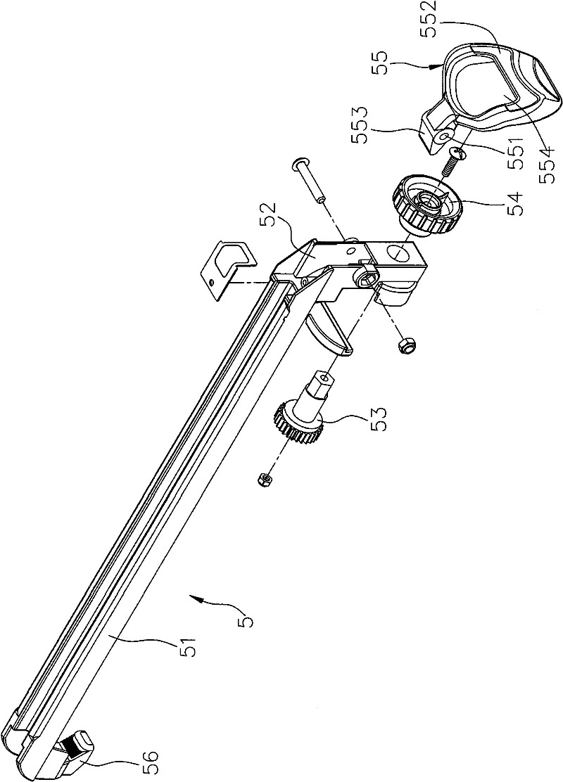
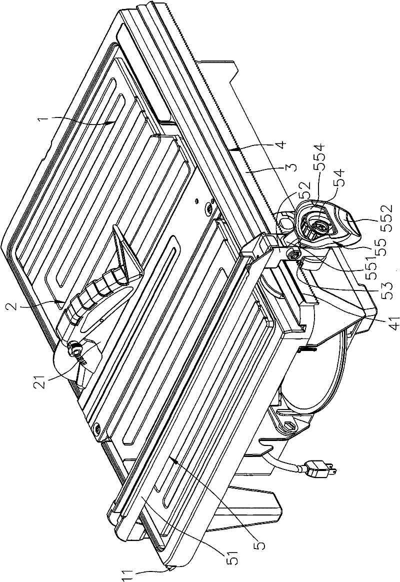
[0026] refer to figure 1 and figure 2 , The first preferred embodiment of the present invention has a cutting machine with a movable leaning plate comprising a workbench 1 , a sawing unit 2 , a guide rail 3 , a blocking flange 4 , and a movable leaning plate unit 5 .

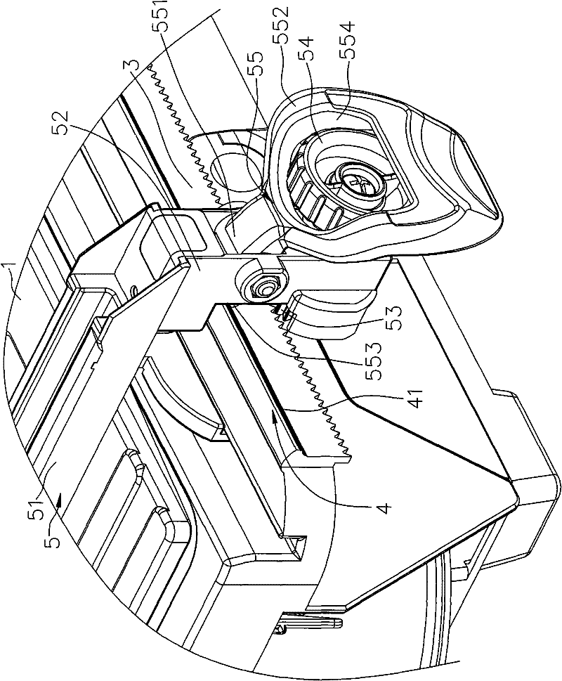
[0027] The sawing unit 2 is installed on the workbench 1 and includes a saw blade 21 . The guide rail 3 is installed on the side edge of the workbench 1, and in this preferred embodiment, the guide rail 3 is a rack. The blocking flange 4 is installed on the side edge of the workbench 1, and the blocking flange 4 includes a plurality of anti-slip lines 41. In this first preferred embodiment, the blocking flange 4 is parallel to the guide rail 3 The direction is set and located above the guide rail 3 .

[0028] The movable backboard unit 5 includes a backboard 51 arranged on the table top of th...


PUM


Abstract

The invention relates to a cutting machine with a movable backup plate, comprising a work table, a saw cutting unit with a saw blade, a guide rail installed at the side edge of the work table and a movable backup plate unit. The movable backup plate unit comprises a backup plate, a gear meshed with the guide rail, a hooking part opposite to the gear and connected with the backup plate, a driving member connected with the gear and a fixing member, wherein the fixing member changes between a locking state and a releasing state relative to the driving member, when being in the locking state, the fixing member approximately limits the driving member and enables the driving member to be locked, when being in the releasing state, the fixing member is away from the driving member, enables the driving member to rotate and drives the backup plate to move, and therefore, a user cannot forget to release the fixing member due to negligence when wanting to rotate the driving member once more to adjust the position of the backup plate, the condition of directly applying force to rotate the driving member in the locking state is avoided, and the user can conveniently adjust the position of the backup plate.

Description

technical field [0001] The invention relates to a cutting machine, in particular to a cutting machine with a movable backing plate. Background technique [0002] An existing cutting machine for cutting workpieces, as disclosed in U.S. Patent No. US6,932,074B2, the user needs to press down to increase the friction between the workpiece and the worktable during cutting, so as to avoid cutting Inappropriate displacement of the workpiece occurs, and in order to assist the user in applying force, a support plate is usually provided on the workbench opposite to the saw blade for the workpiece to lean against, so as to assist the user in applying force more easily. [0003] When cutting workpieces of different widths, the distance between the saw blade and the backing board must also be different. Therefore, the backing board is designed as a movable backing board, allowing users to adjust the position of the backing board according to workpieces of different widths and sizes , bu...

Claims


Application Information

Patent Timeline
Patent Type & Authority Applications(China)
IPC IPC(8): B23D47/04
Inventor 郑志明
Owner REXON IND CORP LTD
Why Eureka
Eureka Blog
Learn More